
Arrangement of supercharging units for supercharging an internal combustion engine

a technology for supercharging units and internal combustion engines, applied in the direction of machines/engines, combustion-air/fuel-air treatment, mechanical equipment, etc., can solve problems such as operational or production costs that are not suitable for supercharging, and achieve the effects of saving construction space, reducing connection costs, and saving construction spa

Active Publication Date: 2008-12-04
BEHR GMBH & CO KG
View PDF12 Cites 4 Cited by
  • Summary
  • Abstract
  • Description
  • Claims
  • Application Information

AI Technical Summary

Benefits of technology

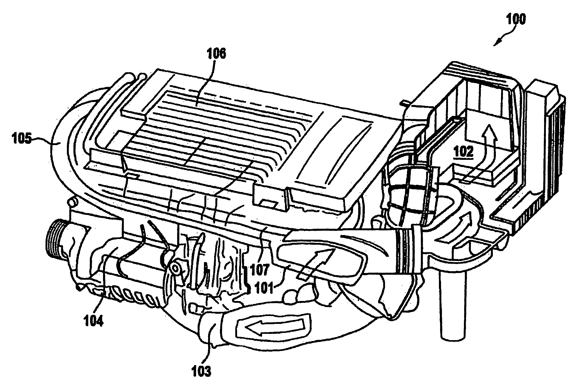
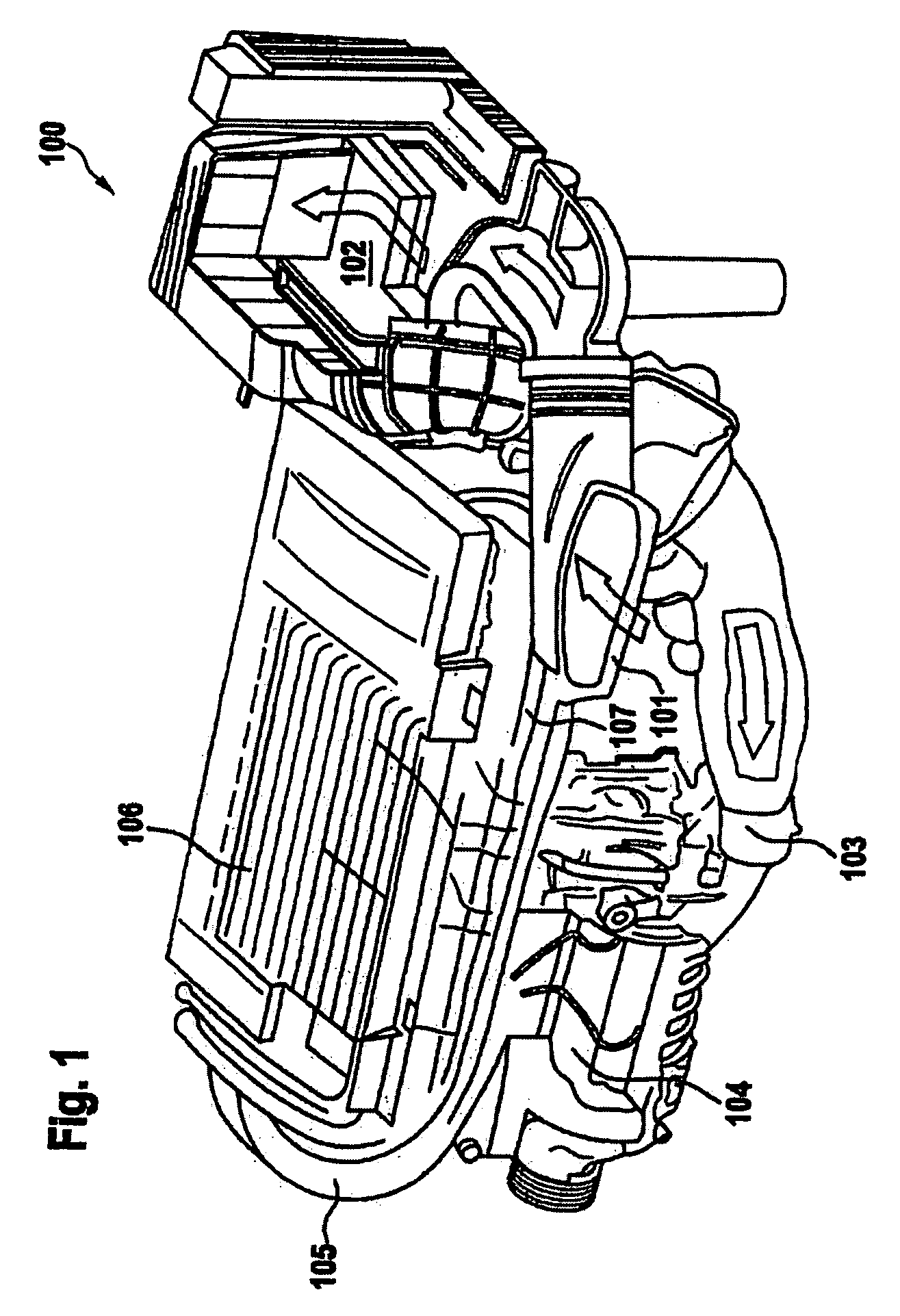
[0006]This is the starting point of the invention, the object of which is to provide a device enabling the supercharging of an internal combustion engine with a fluid comprising charge air and / or exhaust gas to be handled in a manner which saves on construction space and is provided with a comparatively reduced outlay on connection but nevertheless is flexible. It is also the object of the invention to provide an exhaust gas recirculation and / or charge air supply system suitable for this for an internal combustion engine and to provide a corresponding internal combustion engine. It is furthermore the object of the invention to provide a method for producing an exhaust gas recirculation system and / or a charge air supply system, which method saves on construction space, is comparatively simplified, in particular with regard to the outlay on connection and outlay on assembly, and is nevertheless reliable.
[0010]Secondly, there is nevertheless also a considerable simplification of the thermodynamic and structural coordination of the supercharging units and components with one another, in particular at an early point when the supplier has them. The invention has recognized that, in particular in the sphere of the functionality of a charge air supply and / or exhaust gas recirculation, an adequate structural and thermodynamic design with regard to an internal combustion engine can take place, in particular even before the beginning of final assembly. This additionally has the advantage that a structural design of the arrangement of supercharging units for a comparatively small construction space, for example by means of an improved arrangement or shortening of fluid-conducting connections, is possible. In addition, a synergetic further structural and thermodynamic design of the overall arrangement with regard to the overall functionality of a charge air supply and / or an exhaust gas recirculation can already take place before final assembly such that the supercharging units are held together in the module. To this end, the concept of the invention likewise makes provision for the supercharging units to be connected at any rate partially to one another in a fluid-conducting manner, and for at least one of the supercharging units to be held on a holding structure.
[0016]The production method according to the concept of the invention permits the supercharging units and further individual components and connecting parts to be combined with comparatively little outlay and enables optimization of a structural and thermodynamic design. For example, optimization of the construction space requirement, of a connecting length of the in particular fluid-conducting parts or of the preferred arrangement of the module on a preferred side of the engine is possible, if appropriate with the functionality of the supercharging units combined in the module being taken into consideration. A plurality of modules for arrangement on different sides of the engine can also be provided. This type of optimization options results overall in a considerable potential for improvement for energy consumption of the engine, in particular for consumption on the surface of the engine.

Problems solved by technology

Sometimes, the independent positions are comparatively far apart, and therefore this may incur disadvantages with regard to operational or production costs.

Method used


Image

  • Arrangement of supercharging units for supercharging an internal combustion engine
  • Arrangement of supercharging units for supercharging an internal combustion engine
  • Arrangement of supercharging units for supercharging an internal combustion engine

Examples


Embodiment Construction

[0006]This is the starting point of the invention, the object of which is to provide a device enabling the supercharging of an internal combustion engine with a fluid comprising charge air and / or exhaust gas to be handled in a manner which saves on construction space and is provided with a comparatively reduced outlay on connection but nevertheless is flexible. It is also the object of the invention to provide an exhaust gas recirculation and / or charge air supply system suitable for this for an internal combustion engine and to provide a corresponding internal combustion engine. It is furthermore the object of the invention to provide a method for producing an exhaust gas recirculation system and / or a charge air supply system, which method saves on construction space, is comparatively simplified, in particular with regard to the outlay on connection and outlay on assembly, and is nevertheless reliable.

[0007]With regard to the device, the object is achieved by the invention with an a...


PUM


Abstract

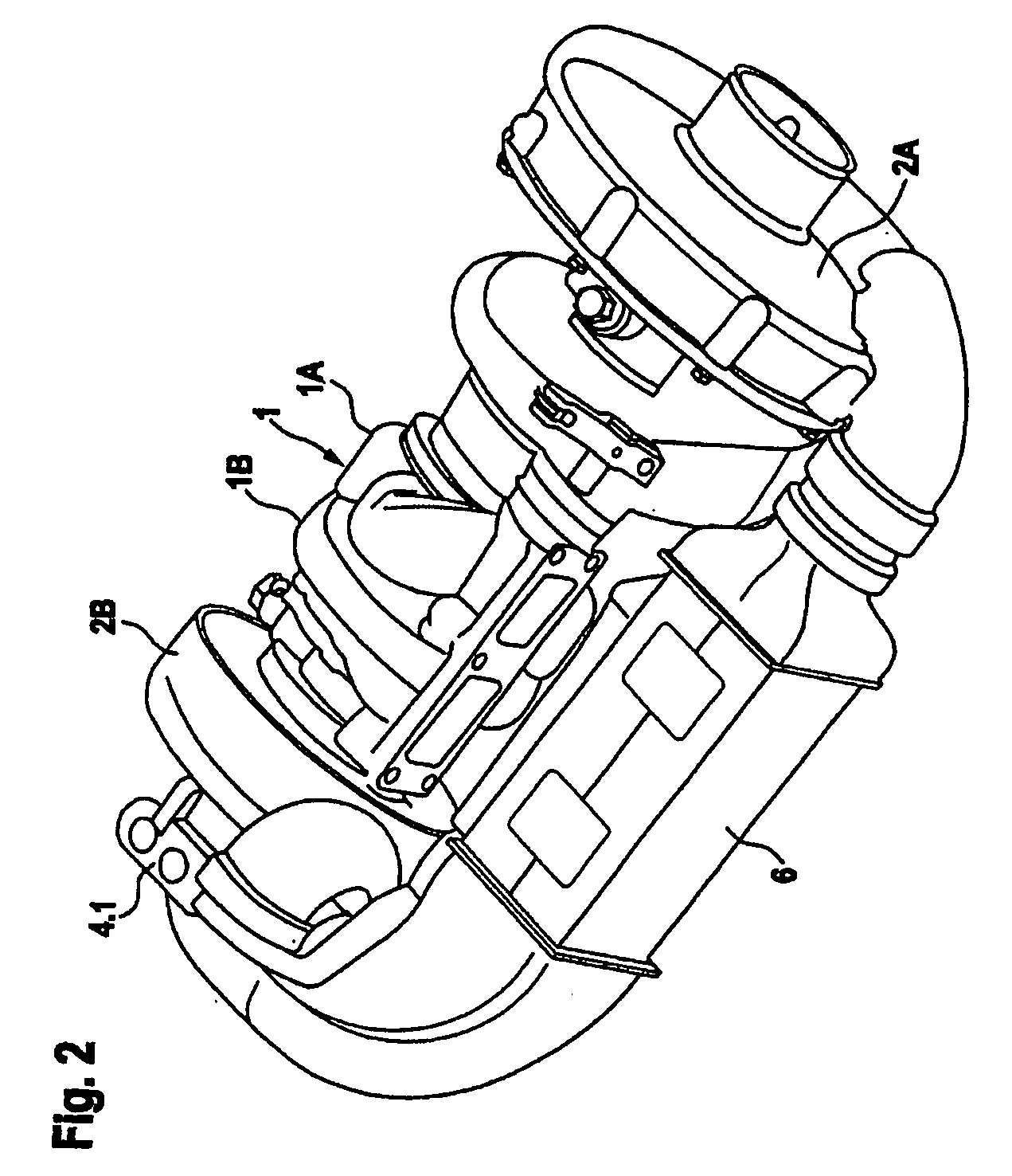
The invention is based on an arrangement of supercharging units (1, 5, 6, 7), which arrangement is to be attached in the construction space of a motor vehicle, for supercharging an internal combustion engine with a fluid (23) comprising charge air and / or exhaust gas, wherein the supercharging units (1, 5, 6, 7) comprise at least one heat exchanger (5, 6, 7) and at least one compressor (1). According to the concept of the invention, the supercharging units (1, 5, 6, 7) are arranged combined in a module (10A, 10B) and, in order for the same to be kept together in the module (10A, 10B), the supercharging units (1, 5, 6, 7) are connected at any rate partially to one another in a fluid-conducting manner, and at least one of the supercharging units (1, 5, 6, 7) is held on a holding structure. This enables the supercharging units to be handled flexibly, simply and nevertheless in a manner saving on construction space and outlay on connection. The invention also leads to a production method.

Description

CROSS-REFERENCE TO RELATED PATENT APPLICATIONS[0001]The right of foreign priority is claimed under 35 U.S.C. § 119(a) based on Federal Republic of Germany Application No. 10 2007 025 173.6, filed May 29, 2007, the entire contents of which, including the specification, drawings, claims and abstract, are incorporated herein by reference.BACKGROUND OF THE INVENTION[0002]The invention relates to an arrangement of supercharging units for supercharging an internal combustion engine with a fluid comprising charge air and / or exhaust gas, wherein the supercharging units comprise at least one heat exchanger and at least one compressor.[0003]To an increasing extent, modular solutions which save on construction space and keep the outlay on connection low are realized within the context of exhaust gas recirculation or charge air supply. The positionings of individual components of an exhaust gas recirculation system or of a charge air supply system, which positionings have hitherto been sometime...

Claims


Application Information

Patent Timeline
IPC IPC(8): F02M25/07F02B37/013
CPCF01N3/043F01P11/04F01P2060/02F01P2060/16F02B29/0412F02B33/34F02B37/013F02B67/10F02M25/0737Y02T10/146Y02T10/144F02M35/042F02M26/32Y02T10/12
Inventor WEGNER, JURGEN
Owner BEHR GMBH & CO KG
Learn More