
Gas sensor having insulator assembly for supporting heater

Inactive Publication Date: 2008-12-04
DENSO CORP
View PDF1 Cites 6 Cited by
  • Summary
  • Abstract
  • Description
  • Claims
  • Application Information

AI Technical Summary

Benefits of technology

[0009]The present invention has been made taking the above mentioned problems into consideration, an object of the present invention is to provide a gas sensor having a holder that is capable of holding an insulator therein and ensuring that a heater electrode formed on a surface of a heater contacts and a sensor electrode formed in a surface of a sensor element with electrode contact members so that it is possible to prevent the gas sensor from being broken even if the gas sensor receives vibration from the outside and to provide reliable electric contact between the heater electrode formed on the surface of the heater and one of the electrode contact member and between the sensor electrode and another electrode contact member.

Problems solved by technology

However, in the gas sensor of Yamada et al., the pressing force generated by the fixing piece of the pressing spring is only utilized to fix the atmosphere side insulator to a position inside the atmosphere side cover.
Thus, the gas sensor of Yamada et al. includes not a small number of springs or members generating pressing force which results in a mechanically complicated supporting structure of the heater and the sensor element in the atmosphere side cover, and the number of the constituents of the gas sensor is increased.
Hence when the gas measurement sensor receives vibration from the outside, the elongated, planar gas sensor may be broken because the connector plug and the spring element cause an unbalance of distribution of mass.

Method used


Image

  • Gas sensor having insulator assembly for supporting heater
  • Gas sensor having insulator assembly for supporting heater
  • Gas sensor having insulator assembly for supporting heater

Examples


first embodiment

[0049]Referring to FIGS. 1-13, a first embodiment of a gas sensor according to the present invention will be described.

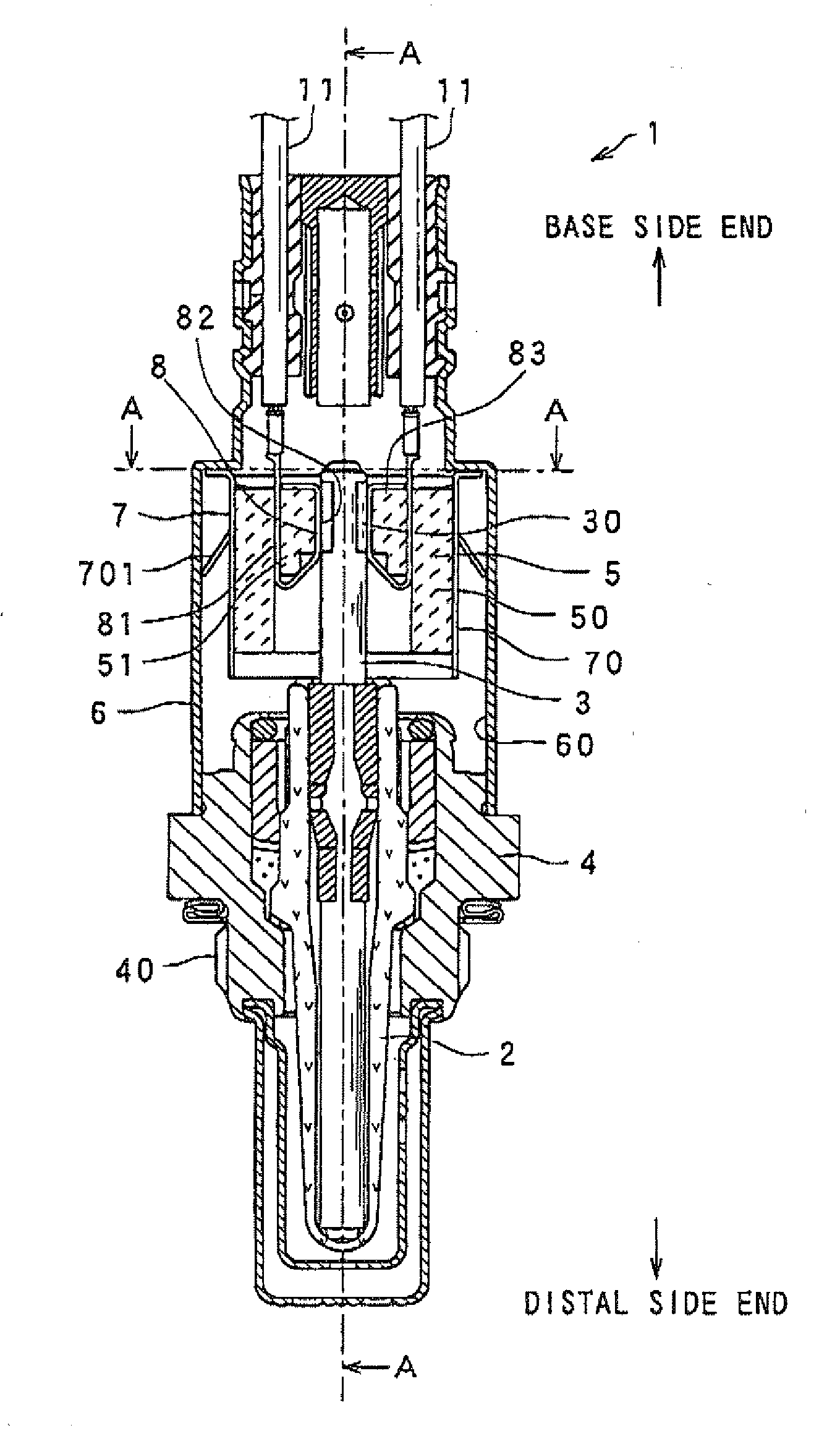
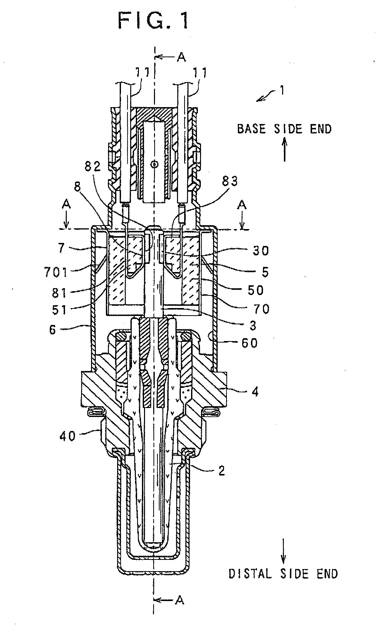
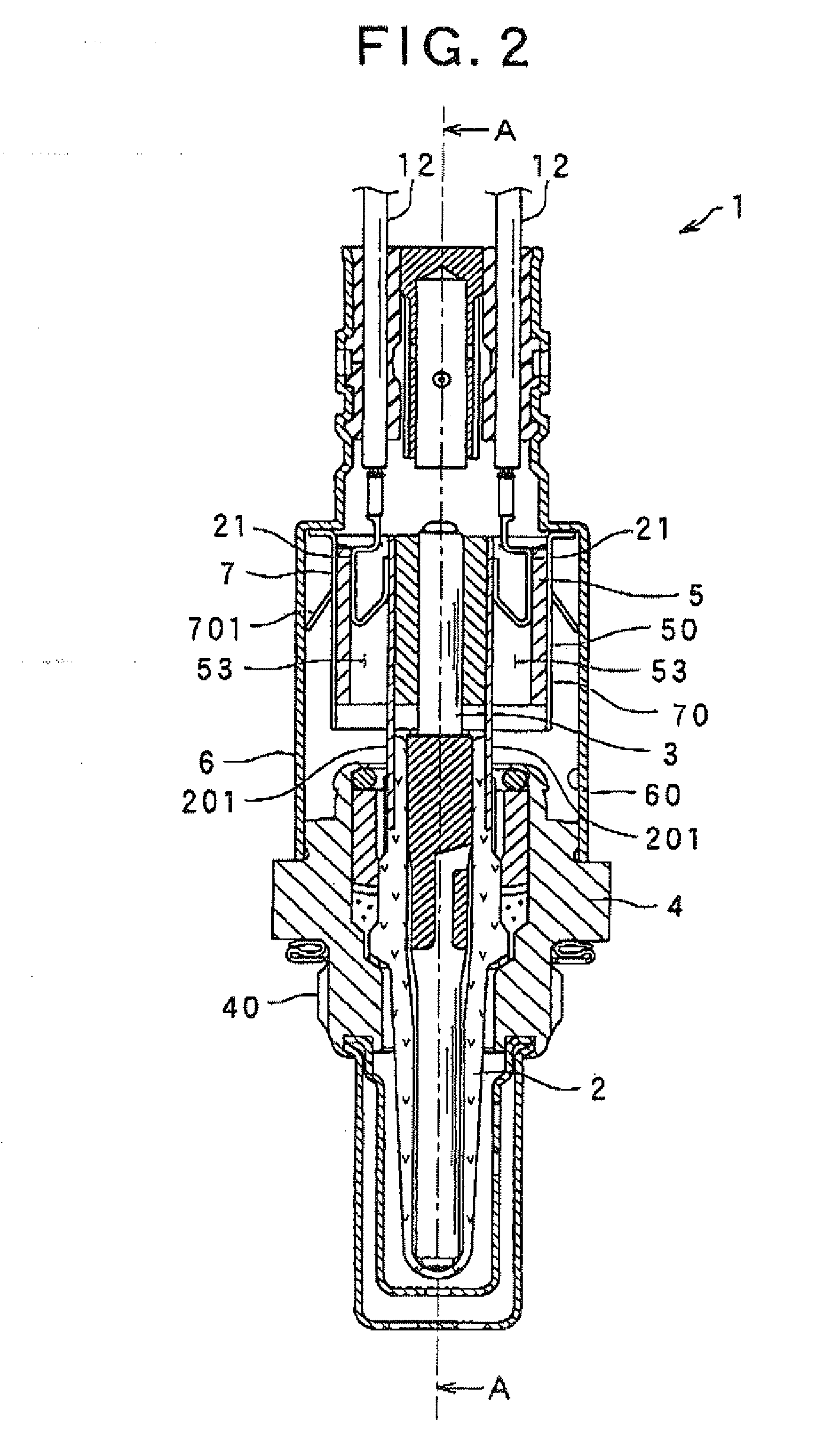
[0050]FIG. 1 is an axial (longitudinal) cross-sectional view showing an overall structure of the gas sensor according to the first embodiment of the present invention. FIG. 2 is an axial (longitudinal) cross-sectional view showing the overall structure of the gas sensor taken on line A-A of FIG. 1.

[0051]As shown in FIGS. 1 and 2, a gas sensor 1 according to the present embodiment includes a sensor element 2, a heater 3, a housing 4, an atmosphere side insulator assembly 5, and an atmosphere side cover 6. The gas sensor 1 has substantially a cylindrical shape and determines the concentration of a specific gas component contained in a measurement gas to be measured. The heater 3 heats up the sensor element 2. The heater 3 is surrounded by the sensor element 2 and has a heater electrode 30 on a peripheral surface of a base end section of the heater 3. The housing 4 has...

second embodiment

[0106]Referring to FIG. 14, a gas sensor 100 according to a second embodiment of the present invention will be described.

[0107]In the second embodiment, the only difference from the first embodiment is based on a shape of the atmosphere side cover 6. Thus, detailed discussion about the constituents of the gas sensor having the same function and the structure with those used in the first embodiment will be omitted.

[0108]FIG. 14 is an axial (longitudinal) cross-sectional view showing an overall structure of the gas sensor 100 according to the second embodiment of the present invention. The gas sensor 100 according to the present embodiment includes an atmosphere side cover 600, while the gas sensor 1 according to the first embodiment includes the atmosphere side cover 6, as shown in FIGS. 1 and 2.

[0109]As shown in FIG. 14, the atmosphere side cover 600 according to the present embodiment has a projection portion 602 formed on the inner peripheral surface 60 of the atmosphere side cove...

third embodiment

[0115]Referring to FIGS. 15-17, a gas sensor 120 according to a third embodiment of the present invention will be described.

[0116]In the third embodiment, the only difference from the previous embodiments is based on a shape of the electrode contact members 8. Thus, detailed discussion about the constituents of the gas sensor having the same function and the structure with those used in the first embodiment will be omitted.

[0117]FIG. 15 is an axial (longitudinal) cross-sectional view showing an overall structure of a gas sensor according to a third embodiment of the present invention and an enlarged axial (longitudinal) sectional view showing the heater, the heater electrodes, and an electrode contact member.

[0118]FIG. 16 is a perspective view showing an electrode contact member 800 according to the third embodiment.

[0119]As shown in FIGS. 15 and 16, the electrode contact member 800 of the gas sensor 120 includes the base plate section 81, an electrode section 802, and the locking s...


PUM


Abstract

There is provided a gas sensor that includes a sensor element, a heater that comprises an electrode, a housing that holds the sensor element therein, an insulator assembly that surrounds a part of the heater and is constituted of a plurality of insulators, an electric terminal member that is located between the one of the plurality of the insulators and the electrode of the heater, a cover that covers the insulator assembly, a holder for holding the insulator assembly, and an elastic member that is located between the holder and the cover to generate elastic force which is applied at least to the one of the plurality of the insulators to pinch the heater between the one and another one of the plurality of the insulators via the holder so as to bring the electric terminal member into constant electric contact with the electrode of the heater.

Description

CROSS REFERENCE TO RELATED APPLICATION[0001]The present application relates to and incorporated by reference Japanese Patent Application No. 2007-148098 filed on Jun. 4, 2007.BACKGROUND OF THE INVENTION[0002]1. The Field of the Invention[0003]The present invention relates to a gas sensor for determining the concentration of a specific gas component contained in a measurement gas to be measured, for example, a gas sensor located in an exhaust system of a vehicle-mounted internal combustion engine for determining a specific gas component in an exhaust gas emitted from the engine[0004]2. Description of the Related Art[0005]In most automobiles, exhaust systems are employed by internal combustion engines, in which the exhaust systems includes a gas sensor installed on an exhaust gas flow passage of the internal combustion engine with a view to determining the concentration of a specific gas component in an exhaust gas emitted from the internal combustion engine (hereinafter, it is someti...

Claims


Application Information

Patent Timeline
IPC IPC(8): G01N27/00
CPCG01N27/4067G01N27/4062
Inventor YAMAUCHI, MASANOBU
Owner DENSO CORP
Learn More