Automatic brazing equipment for copper pipes and joints and its control method

A copper tube and brazing technology, which is applied in the field of automatic brazing equipment for copper tubes and joints and its control, can solve the problems of unfavorable copper tube picking and placing, lower production efficiency, and no detection device, so as to improve the working environment of workers , save manpower and material resources, improve the effect of brazing quality

Active Publication Date: 2022-03-08
XIAMEN UNIV OF TECH
View PDF9 Cites 1 Cited by
  • Summary
  • Abstract
  • Description
  • Claims
  • Application Information

AI Technical Summary

Problems solved by technology

[0005] 1. Putting joints on copper pipes requires manual work, and the production efficiency is low
[0006] 2. When fitting joints on copper pipes, the copper pipes run on the assembly line and need to move with the copper pipes during fitting, which increases the probability of defective fittings and reduces production efficiency
[0007] 3. When the copper tube is fitted to the joint, the copper tube is not fixed, and the copper tube will be displaced during the fitting process, which will affect the welding position, thereby affecting the brazing effect
[0008] 4. If a fixing device is set to fix the copper pipe when fitting the joint, it will increase the complexity of the mechanism and is not conducive to the removal and placement of the copper pipe
[0009] 5. Defective brazing products are usually caused by poor sleeve joints or movement of the welding position, and there is no detection device before brazing, resulting in the detection of defective products after brazing, and the entire copper pipe and joints will be scrapped
[0010] 6. Since the copper pipes with joints enter the heating part of the brazing machine from one side, the heating parts can only be set in a C-shape or U-shape to allow the copper pipes to go in and out of it, but the C-shape or U-shape is not sealed to heat Components will cause uneven heating and affect brazing results

Method used


Image

  • Automatic brazing equipment for copper pipes and joints and its control method
  • Automatic brazing equipment for copper pipes and joints and its control method
  • Automatic brazing equipment for copper pipes and joints and its control method

Examples


Embodiment Construction

[0067] The present invention will be further described in detail below in conjunction with the accompanying drawings and specific embodiments.

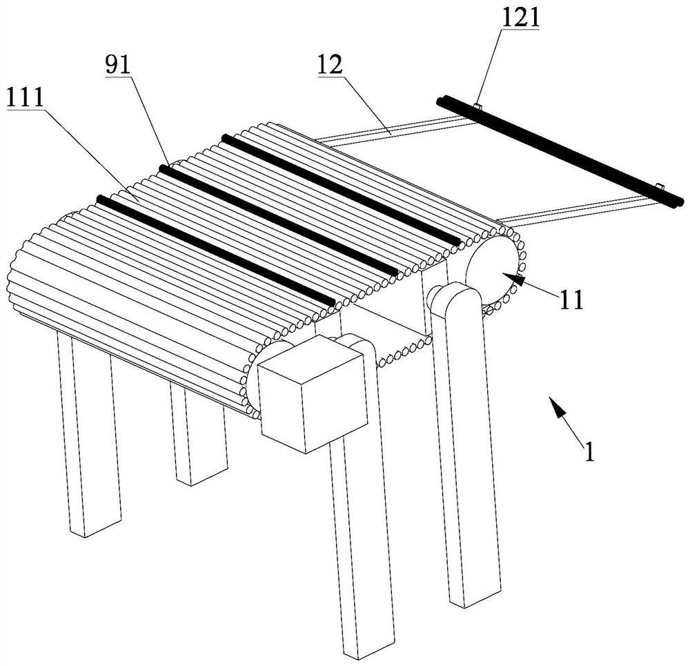
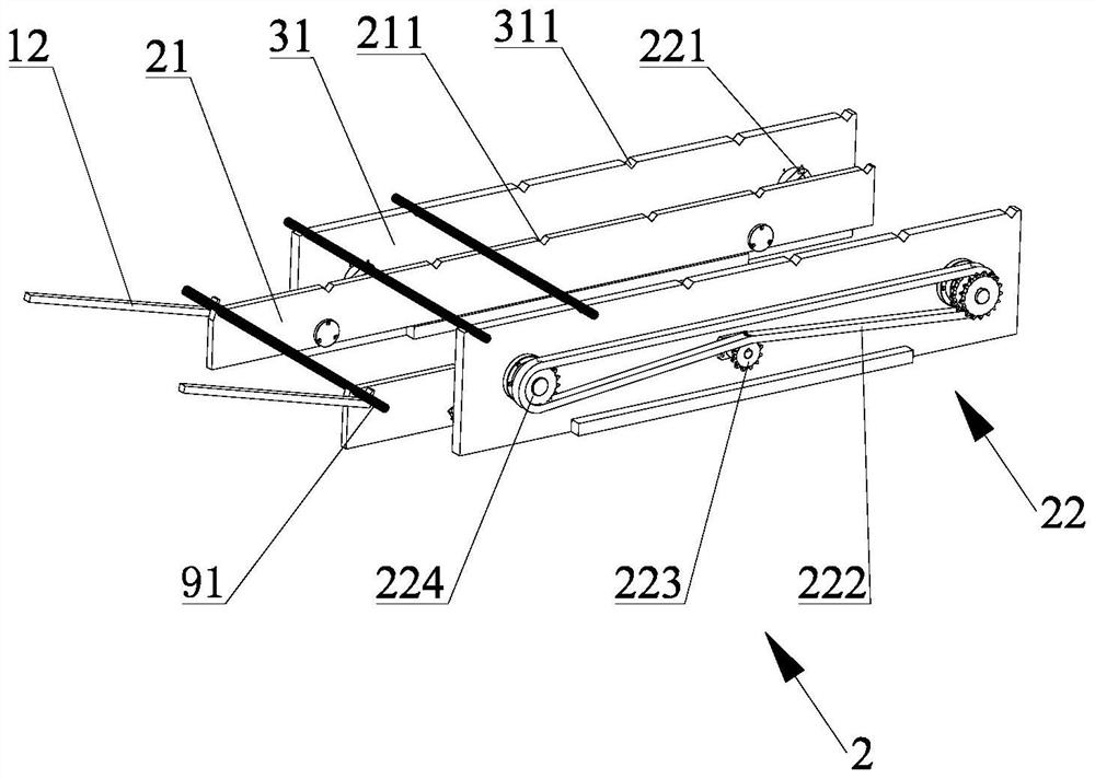
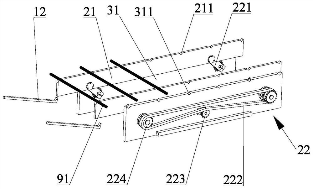
[0068] Disclosed by the present invention is an automatic brazing equipment for copper pipes and joints, such as Figure 1 to Figure 20 Shown is a preferred embodiment of the brazing equipment of the present invention. The automatic brazing equipment includes a copper tube feeding mechanism 1, a copper tube feeding mechanism 2, a copper tube positioning mechanism 3, a joint feeding and fitting mechanism 4, a socket detection mechanism 5, a high frequency brazing machine 6, a blanking Mechanism 7, mobile platform mechanism 8 and control mechanism. The key and focus of the present invention are the copper pipe positioning mechanism 3, the joint feeding and fitting mechanism 4, and the socket detection mechanism 5. The other mechanisms are all auxiliary settings, or are designed to realize full automation, and are not required to be set...


PUM


Abstract

The invention discloses an automatic brazing equipment for copper pipes and joints and a control method thereof. Welding machine; the copper tube delivery mechanism is used to deliver the copper tube to each station; the copper tube positioning mechanism includes a positioning plate and a pressing device for positioning and pressing the copper tube; the joint feeding and assembly The mechanism is used to grab the joint and put the joint on the end of the copper pipe; the socket detection mechanism is used to detect the socket effect of the sleeve joint operation; the high-frequency brazing machine is installed on the brazing machine sliding platform The outer side of the copper tube positioning mechanism is located at the brazing station. The invention can realize a series of operation processes such as automatic feeding and positioning of copper pipes, automatic grasping of joints, detection of sockets and defective sockets, and automatic brazing after that, so as to ensure the welding of copper pipes and joints during the automatic brazing process quality and easy operation.

Description

technical field [0001] The invention relates to the welding technology of copper pipes and their joints, in particular to an automatic brazing equipment for copper pipes and joints and a control method thereof. Background technique [0002] At present, when copper pipes are connected to other tools or workpieces, a joint is usually welded at the interface for easy connection. The commonly used methods are high-frequency induction brazing and flame brazing, and high-frequency induction brazing is a relatively clean welding method. The common method is to first set the brazing ring on the joint, then use a brush to brush a layer of solder paste on the brazing ring on the joint, then put the joint on the copper tube, and finally hold the copper tube on the high-frequency induction welding machine Finish the brazing job. Such a purely manual processing method has low productivity, relatively high production costs, and it is difficult to better guarantee the welding quality. ...

Claims


Application Information

Patent Timeline
Patent Type & Authority Patents(China)
IPC IPC(8): B23K3/00B23K3/08
CPCB23K3/00B23K3/08B23K3/087
Inventor 柯晓龙
Owner XIAMEN UNIV OF TECH
Why Eureka
Try Eureka