
Collapsible slingshot bow

a slingshot bow and collapsible technology, applied in the field of hand-held bows, can solve the problems of inability to adjust, maintain accuracy of projectile trajectory, inability to provide arm rests, and inability to adjust reliability and accuracy, so as to achieve convenient storage and transportation, simple construction, and light weight

Inactive Publication Date: 2008-12-04
TUNDRA QUEST
View PDF13 Cites 17 Cited by
  • Summary
  • Abstract
  • Description
  • Claims
  • Application Information

AI Technical Summary

Benefits of technology

[0008]The present invention provides a sling bow that is simple in construction, light in weight, easy to store and transport, and can be used without modification by a “lefty” or a “righty”.
[0012]In still another aspect of the present invention, the material used for the elastic strap and its manner of attachment to the head portion enables a projectile to be propelled forwardly at speeds greater than the speeds achieved by conventional sling bow devices using similar elastic bands.

Problems solved by technology

Each of the above-mentioned patents has drawbacks, especially with respect to adjustability, reliability and accuracy of shooting.
All of the foregoing patents suffer from the difficulty associated with maintaining accuracy of the projectile trajectory, inasmuch as the arrow rests of the patented devices will not move out of the flight path of the projectile until it is struck by the projectile.
Further, neither Teague nor Miller provide an arm rest to maintain the bow in a steady position while stretching and then releasing the power bands.

Method used


Image

  • Collapsible slingshot bow
  • Collapsible slingshot bow
  • Collapsible slingshot bow

Examples


Embodiment Construction

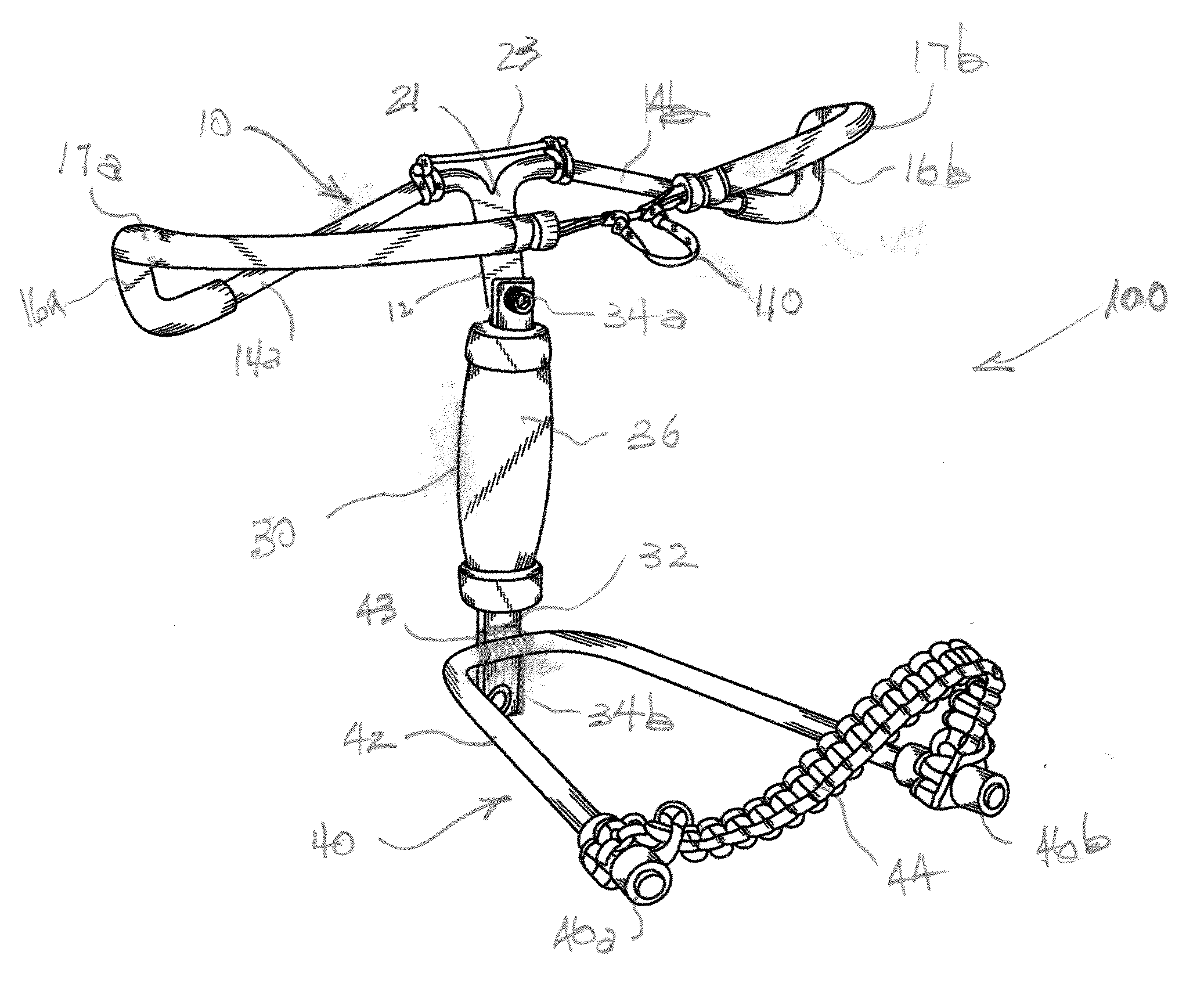
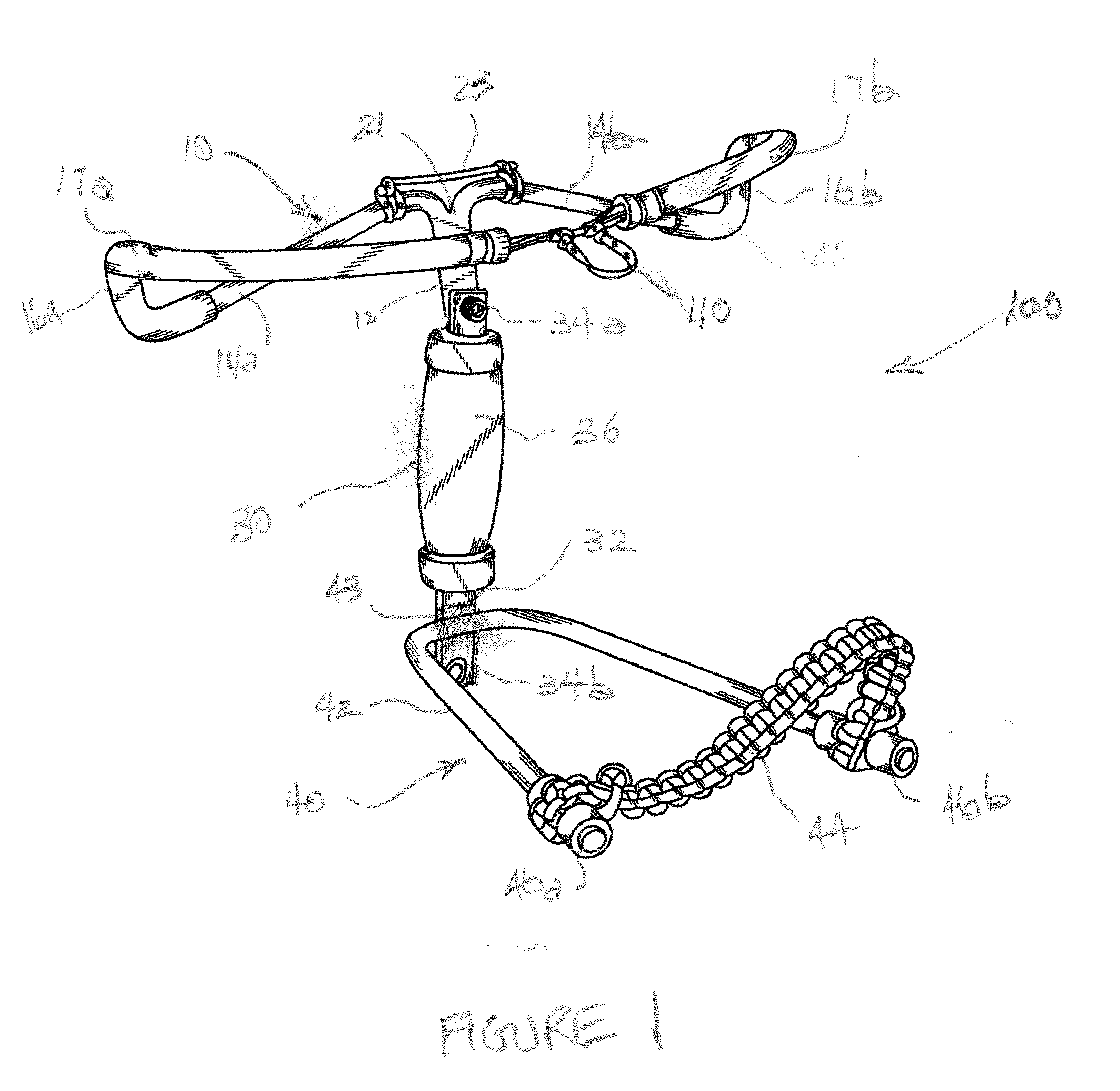
[0025]Referring first to FIG. 1, the sling bow 100 of the present invention is seen to include a bow head 10, a bow handle 30, and a bow arm support 40. It is contemplated that a projectile (not shown), such as a conventional arrow, will be used with the bow of the invention. Such a projectile would include a nock at the end of a shaft that would engage the power band 70 at a nock-engagement portion 85, and would be propelled forwardly of the bow head when the power band is released.

[0026]The bow head 10 includes a frame having central support post 12, and a pair of arms 14a, 14b extending substantially laterally of the central post 12. The end of each arm includes a first short segment 16a, 16b extending substantially normal to a respective arm 14a, 14b. The arm first segments are arranged substantially parallel with one another. The arms, the arm first segments, and the central post together define a substantially planar head portion. At the free end of each first short segment 16...


PUM

PropertyMeasurementUnit
flexibleaaaaaaaaaa
lengthaaaaaaaaaa
distanceaaaaaaaaaa

Abstract

A collapsible slingshot bow for firing an arrow has a head comprising a first U-shaped member including a central post and a pair of arms extending laterally of, and from, the post, the arms terminating in free end portions that extend rearwardly of the post. One end of the post opposite the arms includes a connector, and the head includes a bow string for engaging and launching the arrow. A handle is formed as an elongated handgrip portion having another connector at one end for engagement with connector on the post. An arm support includes a second U-shaped member attached to the handgrip portion via a releasable connector carried by the arm support. A flexible strap having a nock-engaging portion spans the length between the ends of the pair of arms. In using the bow, an archer inserts one of his hands between the ends of the U-shaped member so that his forearm is positioned below the strap; he then grasps the handgrip portion of the handle with the inserted hand thereby securely holding the bow in a fixed position while supporting the bow against his arm so that he can load and launch an arrow with his other hand.

Description

FIELD OF THE INVENTION[0001]The present invention relates to a hand-held bow configured as a sling shot for launching arrows and the like. In comparison to a conventional bow for propelling arrows, a significant advantage of the present slingshot bow is its smallness in size and its being easily and conveniently carried.BACKGROUD OF THE INVENTION[0002]Prior inventions support the notion that smaller bows are inherently advantageous. Various features contribute to the versatility of smaller bows including simplicity of construction, substantial reduction in weight, ease and economy of transport, and ease of use, especially by either a “lefty” (one who uses his / her left arm, hand, leg or foot) or a “righty” (one who uses or favors his right arm, hand, leg or foot) without significant modification.[0003]One example of a known device exhibiting some of these features is the invention disclosed in U.S. Pat. No. 3,018,770 to Saunders for a “SLING SHOT”. The Saunders patent discloses a sli...

Claims


Application Information

Patent Timeline
Patent Type & Authority Applications(United States)
IPC IPC(8): F41F7/00
CPCY10T29/49838F41B3/02
Inventor EDWARDS, RANDY
Owner TUNDRA QUEST
Learn More