Procedures and Compositions for Reservoir Protection

a reservoir and composition technology, applied in the direction of drinking water installation, wellbore/well accessories, construction, etc., can solve the problems of reducing permeability, compromising the ability of wells to flow hydrocarbons, and possible damage to the formation, so as to reduce the viscosity of the drill-in fluid and increase the water viscosity

Active Publication Date: 2008-12-04
BAKER HUGHES INC
View PDF23 Cites 145 Cited by
  • Summary
  • Abstract
  • Description
  • Claims
  • Application Information

AI Technical Summary

Benefits of technology

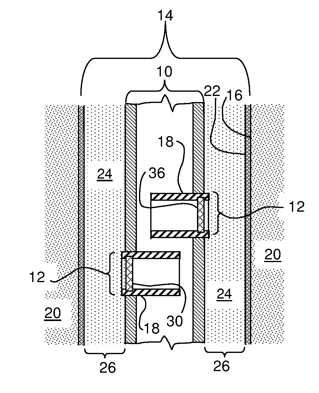
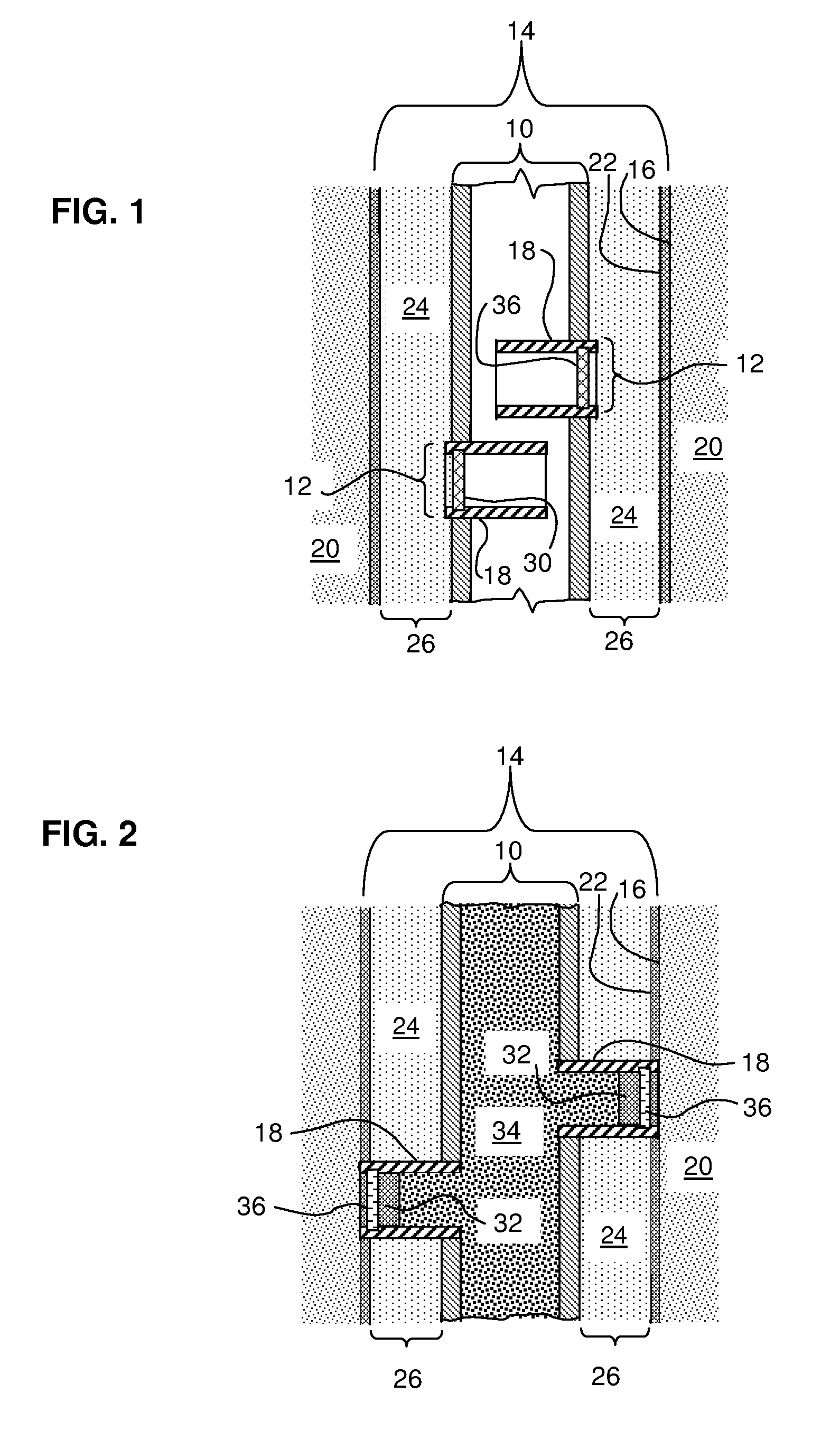
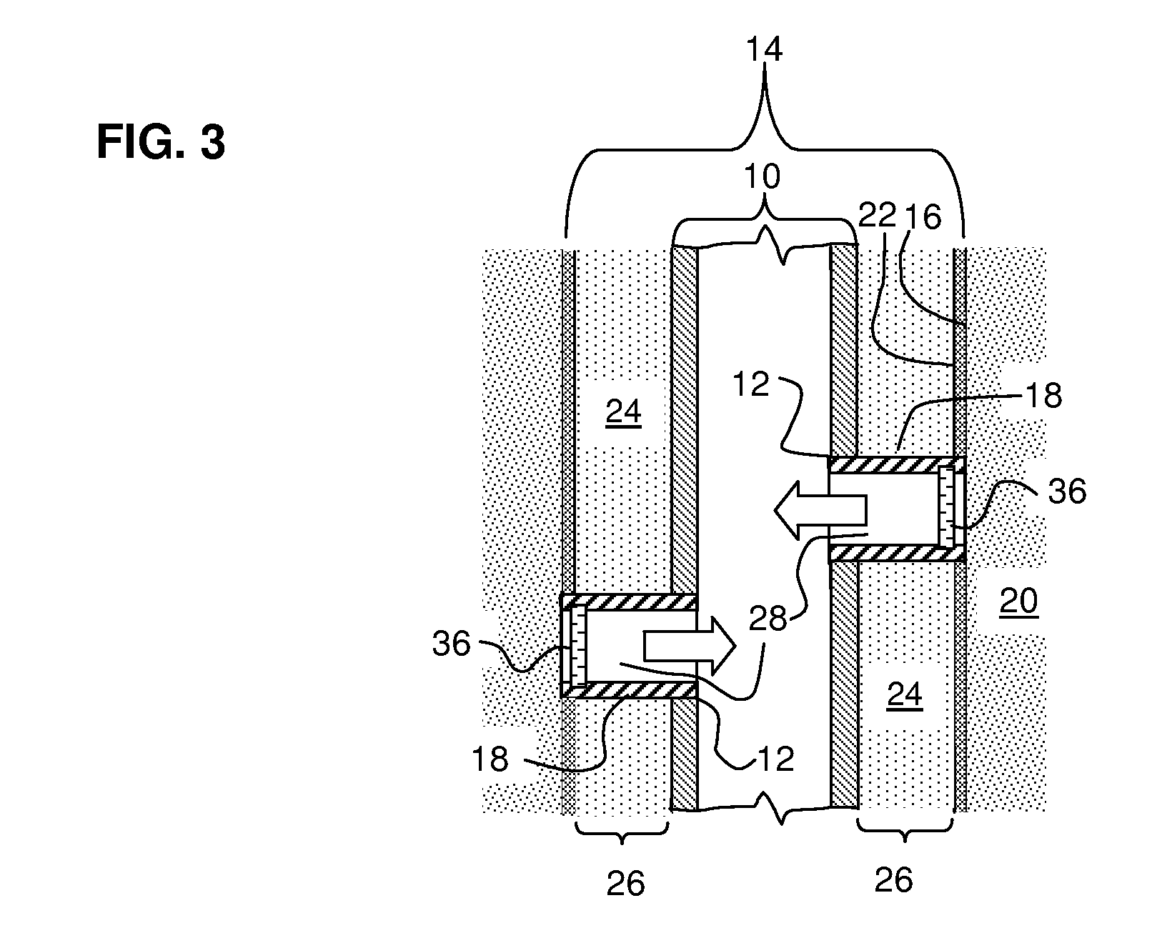
[0009]In carrying out these and other objects of the invention, there is provided, in one non-limiting form, a method for protecting a subterranean reservoir during drilling that involves drilling a well through a subterranean reservoir using a drill-in fluid and a pipe. The drill-in fluid includes water, at least one viscoelastic surfactant (VES) in an amount effective to increase the viscosity of the water, at least one internal breaker, at least one VES stabilizer, at least one viscosity enhancer, and at least one fluid loss control agent. The pipe includes an interior space, an outer surface, and at least one flow conduit between the interior space and the outer surface. In one non-limiting embodiment, the flow conduit is a telescoping sleeve or tube. The flow conduit bears within it a degradable barrier, and the flow conduit is in a retracted position at least partially within the interior space. A drill-in fluid forms a temporary coating (in a non-limiting embodiment, a pseudo-filter cake) over at least a portion of the wellbore wall. The method further involves positioning the pipe within a wellbore that has a wellbore wall at the subterranean reservoir. The degradable barrier is removed from the flow conduit, in one non-limiting embodiment by a fluid such as an acid, solvent and / or by temperature or time. Hydraulic pressure of a fluid, such as or similar to the drill-in fluid previous described, is supplied within the interior space of the pipe and the flow conduit and forms a temporary barrier (e.g. a second pseudofilter cake) in the flow conduit, and is applied to extend the flow conduit in the direction of the wellbore wall. The temporary barrier is removed from the flow conduit to at least partially open the flow conduit. The temporary coating on the well bore wall adjacent the flow conduit is removed, such as by reducing the viscosity of the drill-in fluid. It will be appreciated that the method described above is not necessarily limited to the sequence of the various processes described, and that the method could be practiced effectively with a different sequence of processes or steps.

Problems solved by technology

Such problems include, but are not necessarily limited to, undesirable leak-off of the working fluid into the formation, and possible damage to the formation.
However, a common problem with using polymer-based gelled fluids is that upon removal from the wellbore face damage occurs to the pores of the formation and permeability is reduced, which in turn compromises the wells' ability to flow hydrocarbons.

Method used


Image

  • Procedures and Compositions for Reservoir Protection
  • Procedures and Compositions for Reservoir Protection
  • Procedures and Compositions for Reservoir Protection

Examples


examples

[0096]Shown in FIG. 4 is a graph of fluid leakoff as a function of time through a 400 md ceramic disk at 250° F. (121° C.) and 300 psi (2.1 MPa). The base fluid is 13.0 ppg (1.6 kg / liter) CaCl2 / CaBr2 brine, and includes 4% WG-3L VES and 6 pptg (0.7 kg / m3) VES-STA viscosity stabilizer and 1 gptg GBW-407L fish oil breaker available from Baker Oil Tools. It may be seen that the addition of 10 pptg (1.2 kg / m3) MgO fluid loss control agent (FLCA) greatly reduces the amount of fluid leaked off during the experiment.

[0097]FIG. 5 is another graph of fluid leakoff over time, in this case through a 2000 md ceramic disk at 250° F. (121° C.) and 300 psi (2.1 MPa), where the fluid used is the same as in FIG. 3. Again, it may be seen that the addition of 10 pptg (1.2 kg / m3) MgO fluid loss control agent (FLCA) greatly reduces the amount of fluid leaked off during the experiment.

[0098]Presented in FIG. 6 are two photographs of the same 400 md ceramic disk used in FIG. 3 showing the VES pseudo-filte...


PUM


Abstract

A flow conduit having at least one orifice is placed in the vicinity of a flow source, which in one non-limiting embodiment may be a hydrocarbon reservoir. The flow pathway between the orifice and the source is temporarily blocked with a degradable barrier. Once the flow pathway is physically placed, the degradable barrier is removed under the influence of an acid, a solvent, time and/or temperature. The flow source and the flow pathways are at least partially covered (and flow blocked by) a temporary coating such as a pseudo-filter cake formed by a viscoelastic surfactant-gelled aqueous drill-in fluid, and the flow conduit is extended to the flow source. The pseudo-filter cake is removed when viscosity is reduced by an internal breaker, and flow is then allowed. The method is useful in one context of recovering hydrocarbons where the flow conduit is a telescoping sleeve or tube that contacts the borehole wall.

Description

TECHNICAL FIELD[0001]The present invention relates to methods and compositions for protecting a reservoir from damage during drilling-in, completion and production operations, and more particularly relates, in one embodiment, to methods and compositions for inhibiting or preventing reservoir damage using a drill-in fluid gelled with a viscoelastic surfactant.TECHNICAL BACKGROUND[0002]There are a number of procedures and applications that involve the formation of a temporary seal, coating or plug while other steps or processes are performed, where the seal, coating or plug must be later removed. Often such seals or plugs are provided to temporarily inhibit or block a flow pathway or the movement of fluids or other materials, such as flowable particulates, in a particular direction for a short period of time, when later movement or flow is desirable.[0003]A variety of applications and procedures where temporary coatings or plugs are employed are involved in the recovery of hydrocarbon...

Claims


Application Information

Patent Timeline
Patent Type & Authority Applications(United States)
IPC IPC(8): E21B37/08
CPCC09K8/506C09K8/68E21B33/138E21B37/08E21B43/11
Inventor HUANG, TIANPINGCREWS, JAMES B.
Owner BAKER HUGHES INC
Why Eureka
Try Eureka