Heat processing furnace and method of manufacturing the same

a technology of heat processing furnace and heat resistor, which is applied in the direction of furnace heating elements, furnaces, lighting and heating apparatus, etc., can solve the problems of deterioration in durability (reduction in lifetime), deterioration in durability of heating resistors, etc., and achieve the effect of improving durability

Active Publication Date: 2008-12-04
TOKYO ELECTRON LTD
View PDF1 Cites 29 Cited by
  • Summary
  • Abstract
  • Description
  • Claims
  • Application Information

AI Technical Summary

Benefits of technology

[0007]The present invention has been made in view of the above circumstances. The object of the present invention is to provide a heat processing furnace and a method of manufacturing the same, capable of reducing a frictional resistance, which is generated between a support member and a heating resistor when the heating resistor is thermally expanded and thermally shrunk, so that generation of a permanent deformation of the heating resistor caused by a residual stress thereof can be restrained to thereby improve durability of the heating resistor.
[0011]The present invention is the heat processing furnace, wherein: a linear member for preventing falling of the heating resistor is disposed between the inner ends of the tubular members, which are adjacent to each other in an up and down direction; and the linear member passes through shaft holes of the upper and the lower tubular members so as to be embedded and fixed in the heat insulation member.
[0012]The present invention is the heat processing furnace, wherein a support column for preventing falling of the heating resistor is disposed on the inner ends of the tubular members, which are arranged in an up and down direction.
[0013]The present invention is the heat processing furnace, wherein an annular member for preventing falling of the heating resistor is fitted in the inner end of each of the tubular members.
[0018]According to the present invention, since a frictional resistance, which is generated between a support member and a heating resistor when the heating resistor is thermally expanded and thermally shrunk, can be reduced, generation of a permanent deformation of the heating resistor caused by a residual stress thereof can be restrained, to thereby improve the durability.

Problems solved by technology

In this case, the heating resistor undergoes a permanent deformation caused by a residual stress, which invites deterioration in durability (reduction in lifetime).
In particular, when the heating resistor is heated to be thermally expanded and then cooled to be thermally shrunk, there is a tendency that a permanent elongation (permanent deformation) of the heating resistor is promoted by the residual stress caused by the frictional resistance between the support member and the heating resistor, resulting in deterioration in durability of the heating resistor.

Method used


Image

  • Heat processing furnace and method of manufacturing the same
  • Heat processing furnace and method of manufacturing the same
  • Heat processing furnace and method of manufacturing the same

Examples


Embodiment Construction

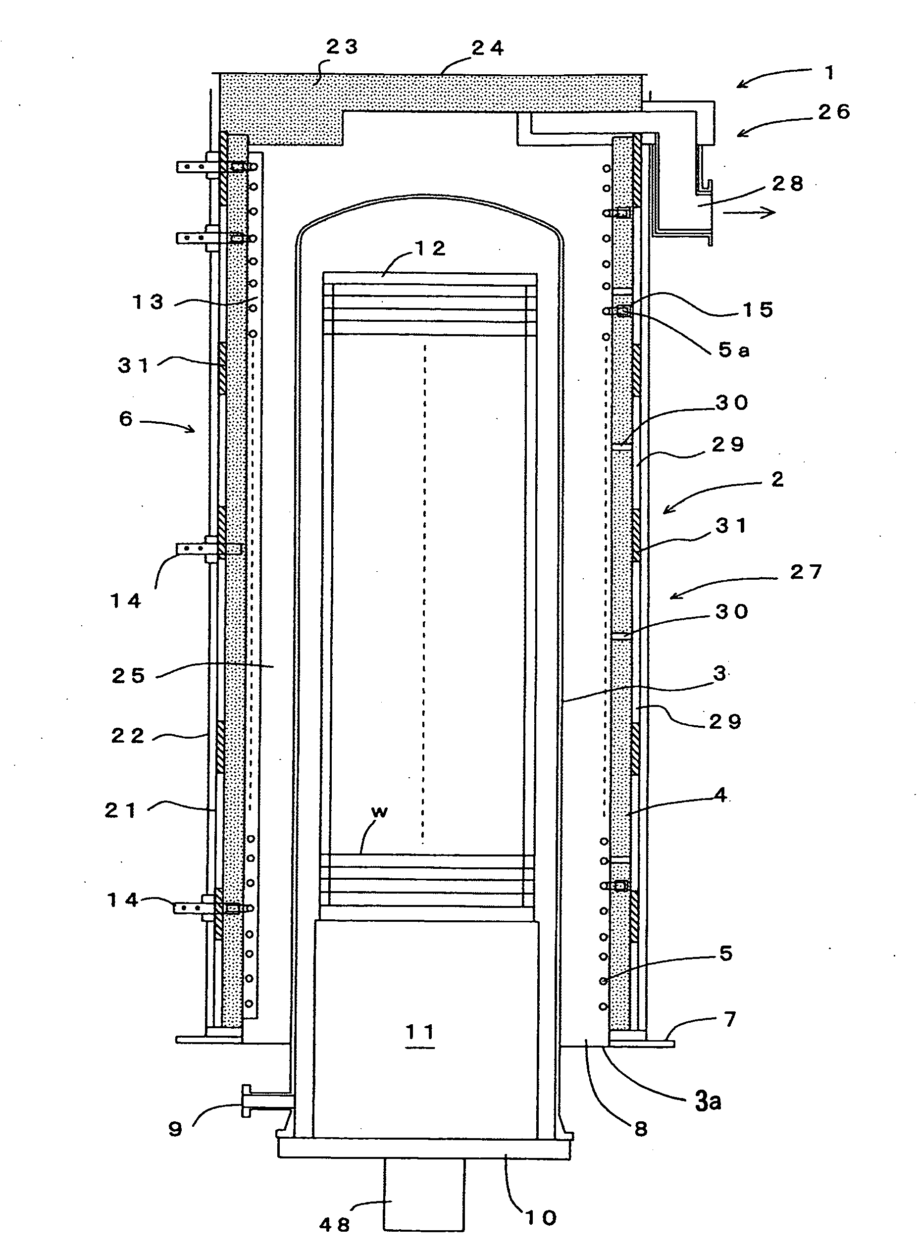
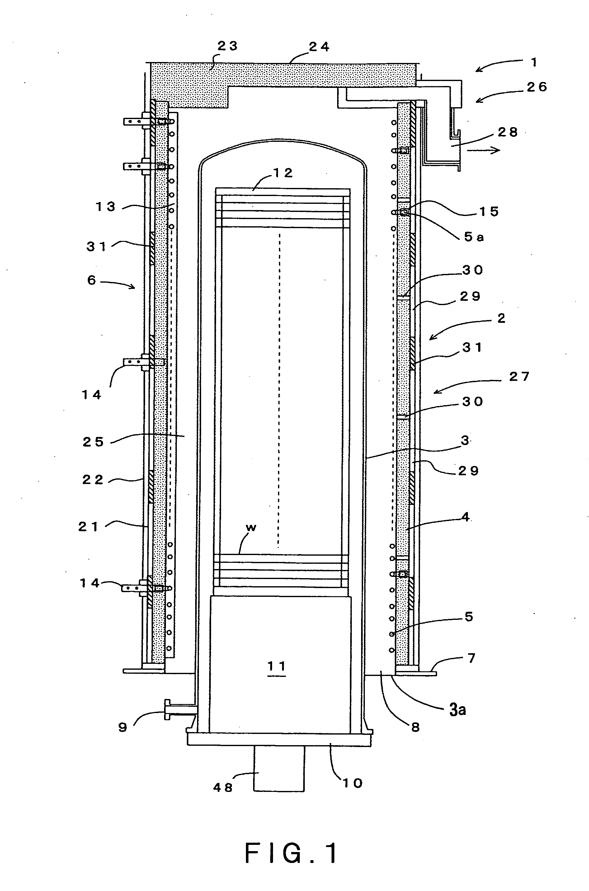
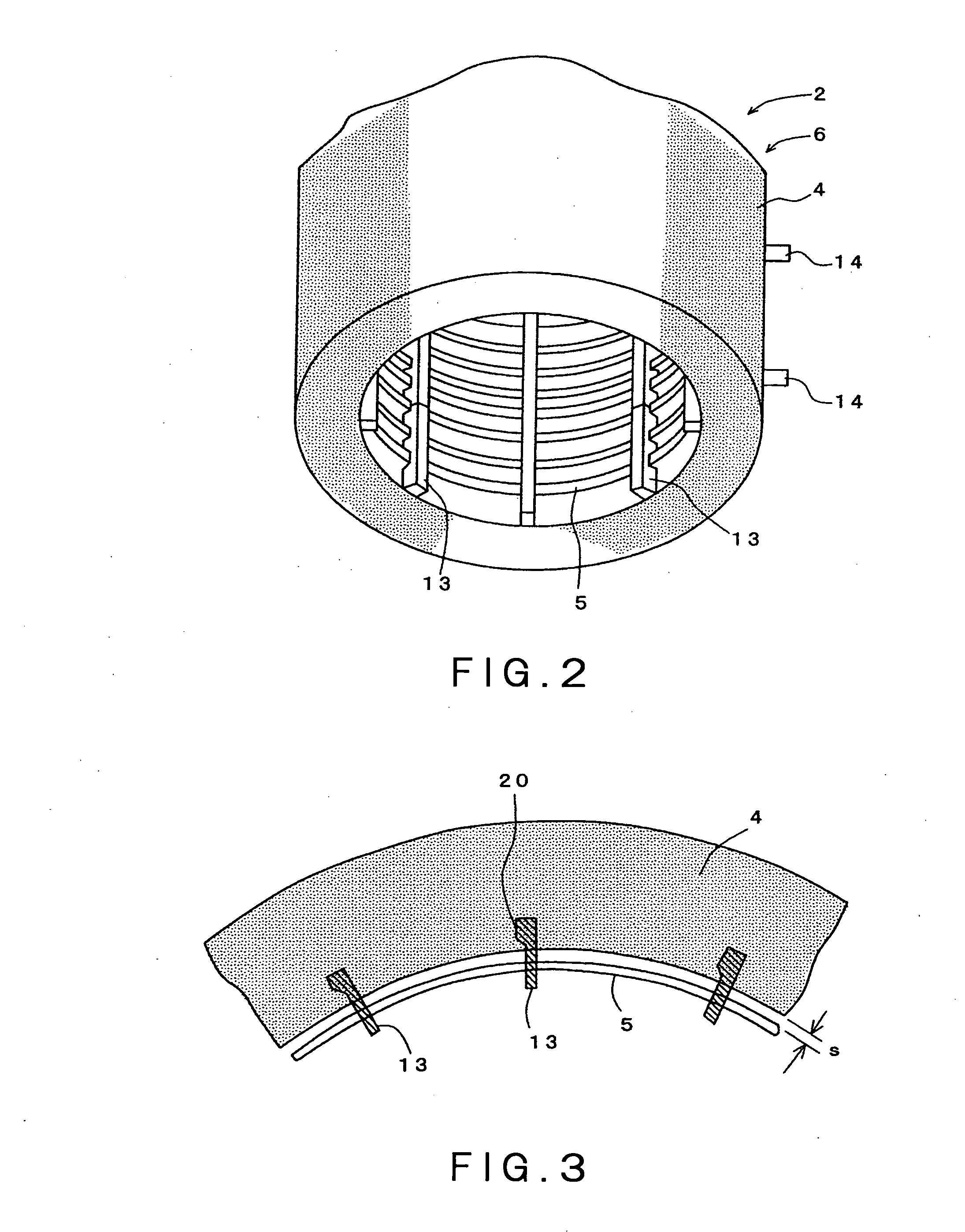
[0042]The best mode for carrying out the invention will be described herebelow with reference to the accompanying drawings. FIG. 1 is a longitudinal sectional view schematically showing a heat processing furnace in one embodiment according to the present invention. FIG. 2 is a perspective view partially showing the heat processing furnace. FIG. 3 is a partial cross-sectional view of the heat processing furnace. FIG. 4 is a partial longitudinal sectional view of the heat processing furnace.

[0043]In FIG. 1, the reference number 1 shows a vertical heat processing apparatus which is one of semiconductor manufacturing apparatuses. The heat processing apparatus 1 is formed of a vertical heat processing furnace 2 capable of simultaneously accommodating a number of objects to be processed, such as semiconductor wafers w, and performing a heat process such as an oxidation process, a diffusion process, and a low pressure CVD process. The heat processing furnace 2 includes a processing vessel ...


PUM

PropertyMeasurementUnit
temperatureaaaaaaaaaa
pressureaaaaaaaaaa
diameteraaaaaaaaaa

Abstract

The object of the present invention is to reduce a frictional resistance which is generated between a support member and a heating resistor when the heating resistor is thermally expanded and thermally shrunk, whereby generation of a permanent deformation of the heating resistor caused by a residual stress thereof can be restrained, to thereby improve the durability. A heat processing furnace comprises: a processing vessel 3 capable of accommodating an object to be processed w and subjecting the object to be processed w to a heat process; a cylindrical heat insulation member 4 surrounding the processing vessel 3; a helical heating resistor 5 arranged along an inner peripheral surface of the heat insulation member 4; a support member 13 disposed on the inner peripheral surface of the heat insulation member 4 in parallel with an axial direction thereof, for supporting the heating resistor 5 at predetermined pitches along the axial direction; and a plurality of terminal plates 14 axially arranged on an outside of the heating resistor 5 at suitable intervals therebetween, the terminal plates 14 radially passing through the heat insulation member 4 so as to be extended outside. The support member 13 includes a base part 17 positioned on an inside of the heating resistor 5, and a plurality of support pieces 18 extending radially outward from the base part through spaces between adjacent portions of the heating resistor 5 so as to support the heating resistor 5, the support member 13 being formed to have a comb-like shape. An upper surface part of each of the support pieces 18 is formed to have a curved shape in order to reduce a frictional resistance generated when the heating resistor 5 is moved upon a thermal expansion and a thermal shrinkage thereof.

Description

CROSS REFERENCE TO RELATED APPLICATIONS[0001]This application is based upon and claims the benefit of priority from the prior Japanese Patent Application No. 2007-146733 filed on Jun. 1, 2007, the entire contents of which are incorporated herein by reference.FIELD OF THE INVENTION[0002]The present invention relates to a heat processing furnace and a method of manufacturing the same.BACKGROUND ART[0003]When a semiconductor device is manufactured, various kinds of heat processing apparatuses are employed for subjecting a semiconductor wafer, which is an object to be processed, to processes such as an oxidation process, a diffusion process, and a CVD (Chemical Vapor Deposition) process. A general heat processing apparatus includes a heat processing furnace which is composed of: a processing vessel (also referred to as “reaction tube”) in which a semiconductor wafer can be accommodated and heat-processed; a heating resister (also referred to as “heating wire” or “element”) disposed arou...

Claims


Application Information

Patent Timeline
Patent Type & Authority Applications(United States)
IPC IPC(8): F27D11/00H05B3/02
CPCF27B17/0025Y10T29/49083H01L21/67109
Inventor KOBAYASHI, MAKOTONAKAO, KEN
Owner TOKYO ELECTRON LTD
Why Eureka
Try Eureka