Continuous infrared furnace
- Summary
- Abstract
- Description
- Claims
- Application Information
AI Technical Summary
Benefits of technology
Problems solved by technology
Method used
Image
Examples
Embodiment Construction
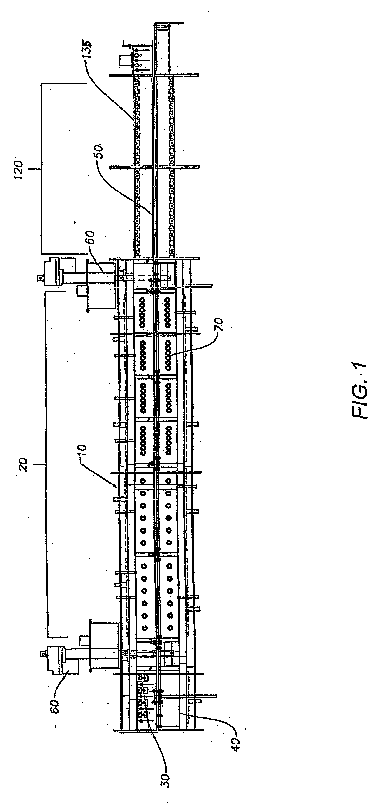
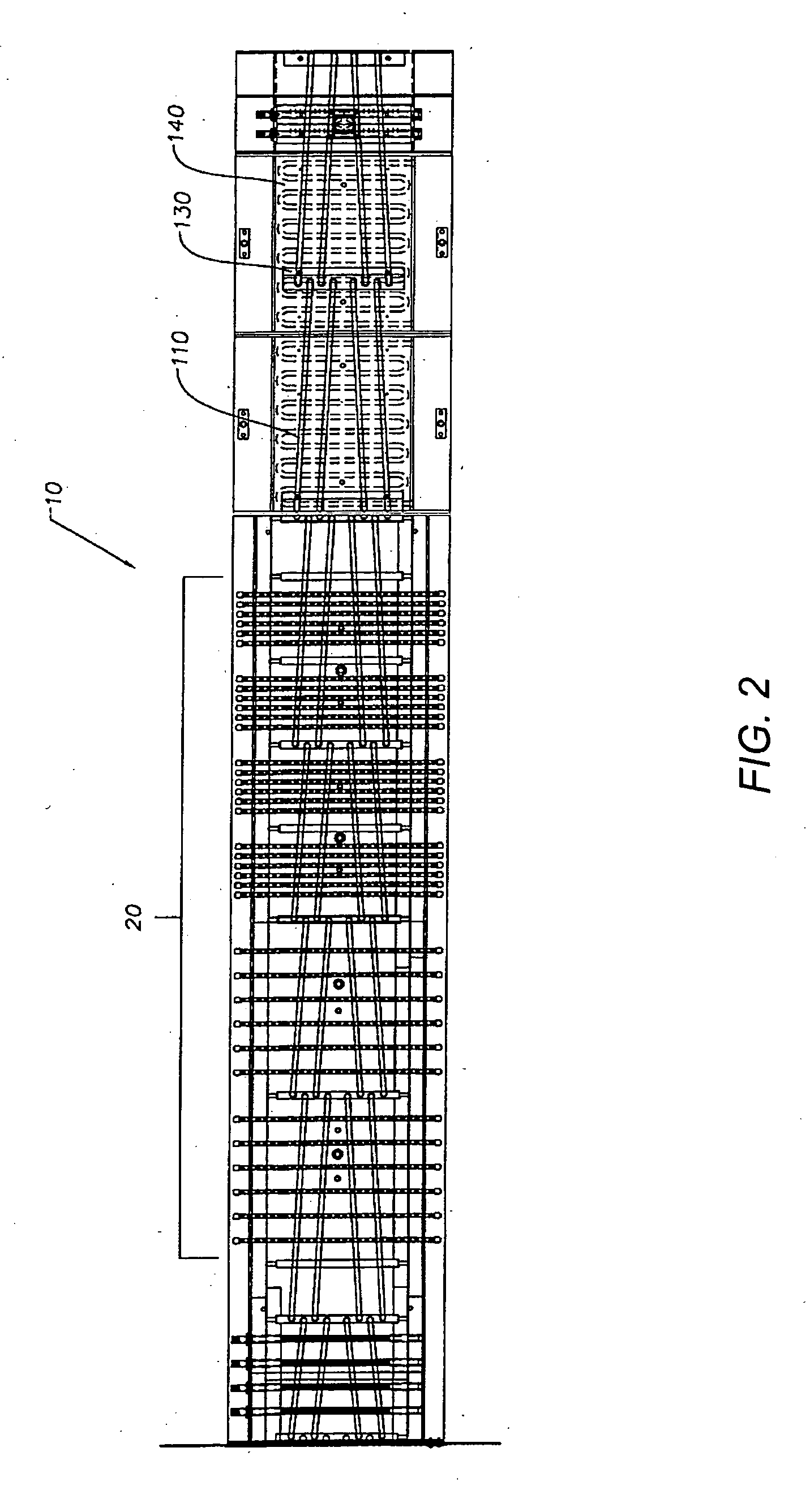
[0017]Turning now to the figures, FIG. 1 is a side view of an embodiment of a furnace in accordance with the invention. The furnace 10 has a heat transfer zone generally indicated at 20 for heating a material to be treated (not shown). The heat transfer zone 20 has an upper portion 30 and a lower portion 40. A conveyor 50 transports material to be treated through heat transfer zone 20 along a direction of travel. The conveyor 50 may be, for example, a conveyor belt, a walking beam, or other conveyor known in the art. A jack 60 allows movement of the lower portion 40 of the heat transfer zone 20 to allow access to the interior of the heat transfer zone 20 and to components therein. A jack 60, as used in this application, means a device for raising and lowering objects by means of force applied with a lever, screw, hydraulic press, or other means known in the art. The heat transfer zone 20 may also include one or more infrared lamps 70. These infrared lamps may be, for example, quartz...
PUM
| Property | Measurement | Unit |
|---|---|---|
| pressure | aaaaa | aaaaa |
| pressure | aaaaa | aaaaa |
| heat | aaaaa | aaaaa |
Abstract
Description
Claims
Application Information
 - R&D
- Intellectual Property
- Life Sciences
- Materials
- Tech Scout
- Unparalleled Data Quality
- Higher Quality Content
- 60% Fewer Hallucinations
Browse by: Latest US Patents, China's latest patents, Technical Efficacy Thesaurus, Application Domain, Technology Topic, Popular Technical Reports.
© 2025 PatSnap. All rights reserved.Legal|Privacy policy|Modern Slavery Act Transparency Statement|Sitemap|About US| Contact US: help@patsnap.com


