Fuel metering valve back-up position control system

Inactive Publication Date: 2008-12-04
HONEYWELL INT INC
View PDF28 Cites 30 Cited by
  • Summary
  • Abstract
  • Description
  • Claims
  • Application Information

AI Technical Summary

Benefits of technology

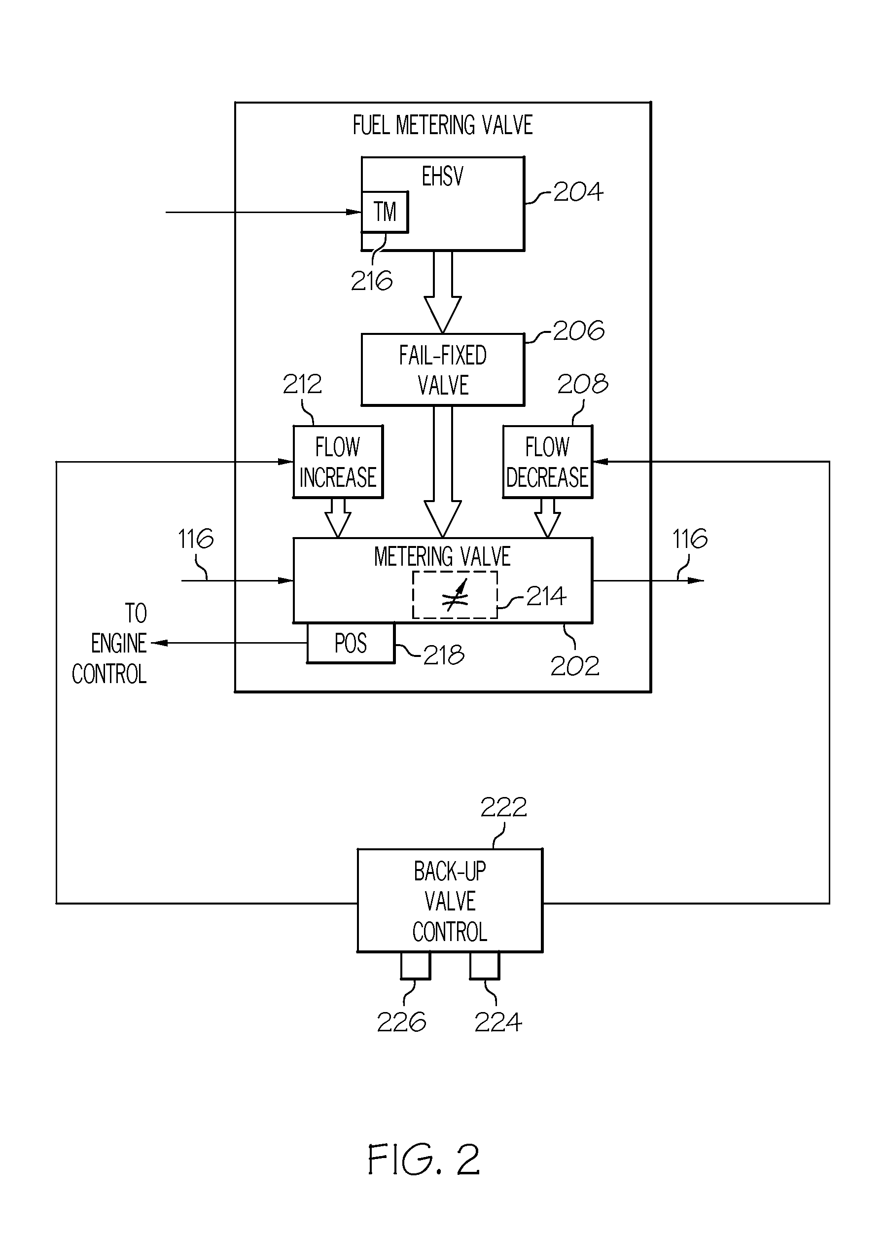
[0006]The present invention provides a system that allows a pilot to manually manipulate fuel flow to the engine during the loss of power to the fuel metering unit. In one embodiment, and by way of example only, a fuel metering unit includes a fuel metering valve, a metering valve actuator, a fail-fixed valve, a flow increase valve, and a flow decrease valve. The fuel metering valve is adapted to receive a flow of fuel from a fuel source and has a variable area flow orifice through which fuel from the fuel source flows. The fuel metering valve is coupled to receive hydraulic fluid and is operable, upon receipt of the hydraulic fluid, to adjust the area of the variable area flow orifice based in part on the pressure of the hydraulic fluid. The metering valve actuator is adapted to receive fuel flow command signals and hydraulic fluid from one or more hydraulic fluid sources. The metering valve actuator is operable, upon receipt of the fuel flow command signals and the hydraulic fluid, to supply variable pressure hydraulic fluid to the fuel metering valve. The fail-f

Problems solved by technology

Fuel supply and engine control systems, such as the one described above, may experience certain postulated events that may result in certain postulated failure modes, which in turn may result in certain postul

Method used


Image

  • Fuel metering valve back-up position control system
  • Fuel metering valve back-up position control system
  • Fuel metering valve back-up position control system

Examples


Embodiment Construction

[0013]The following detailed description of the invention is merely exemplary in nature and is not intended to limit the invention or the application and uses of the invention. Furthermore, there is no intention to be bound by any theory presented in the preceding background of the invention or the following detailed description of the invention.

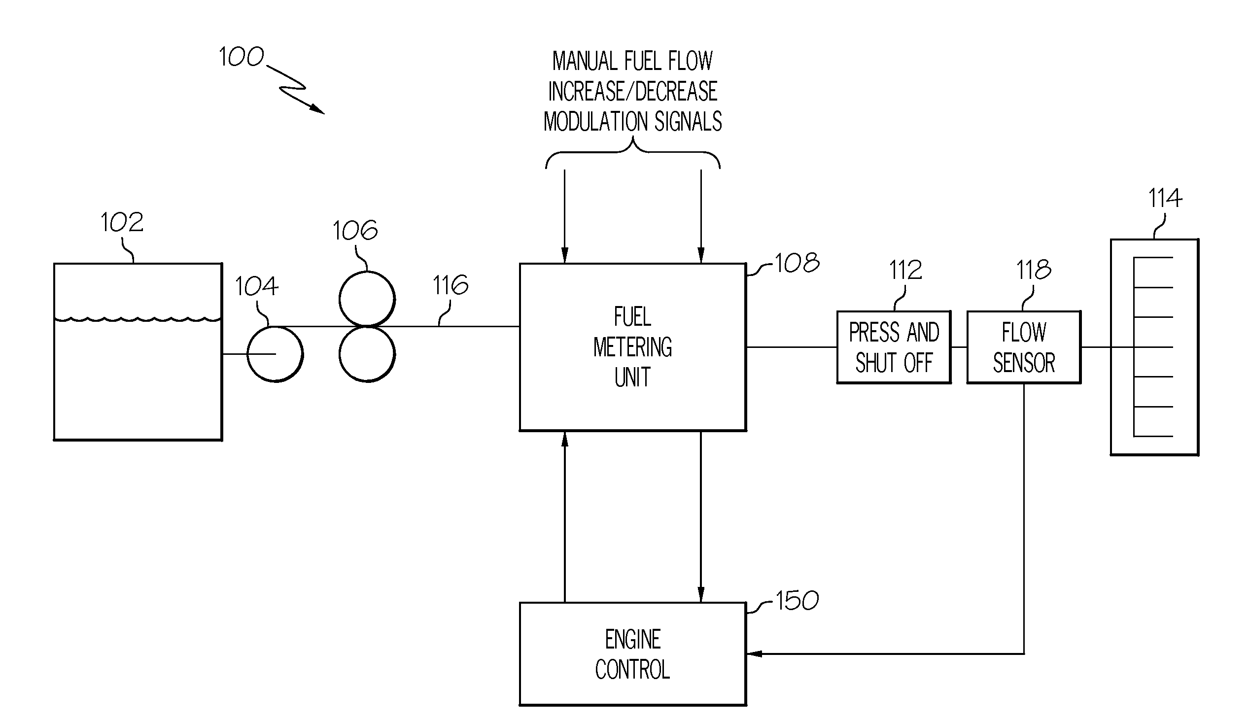
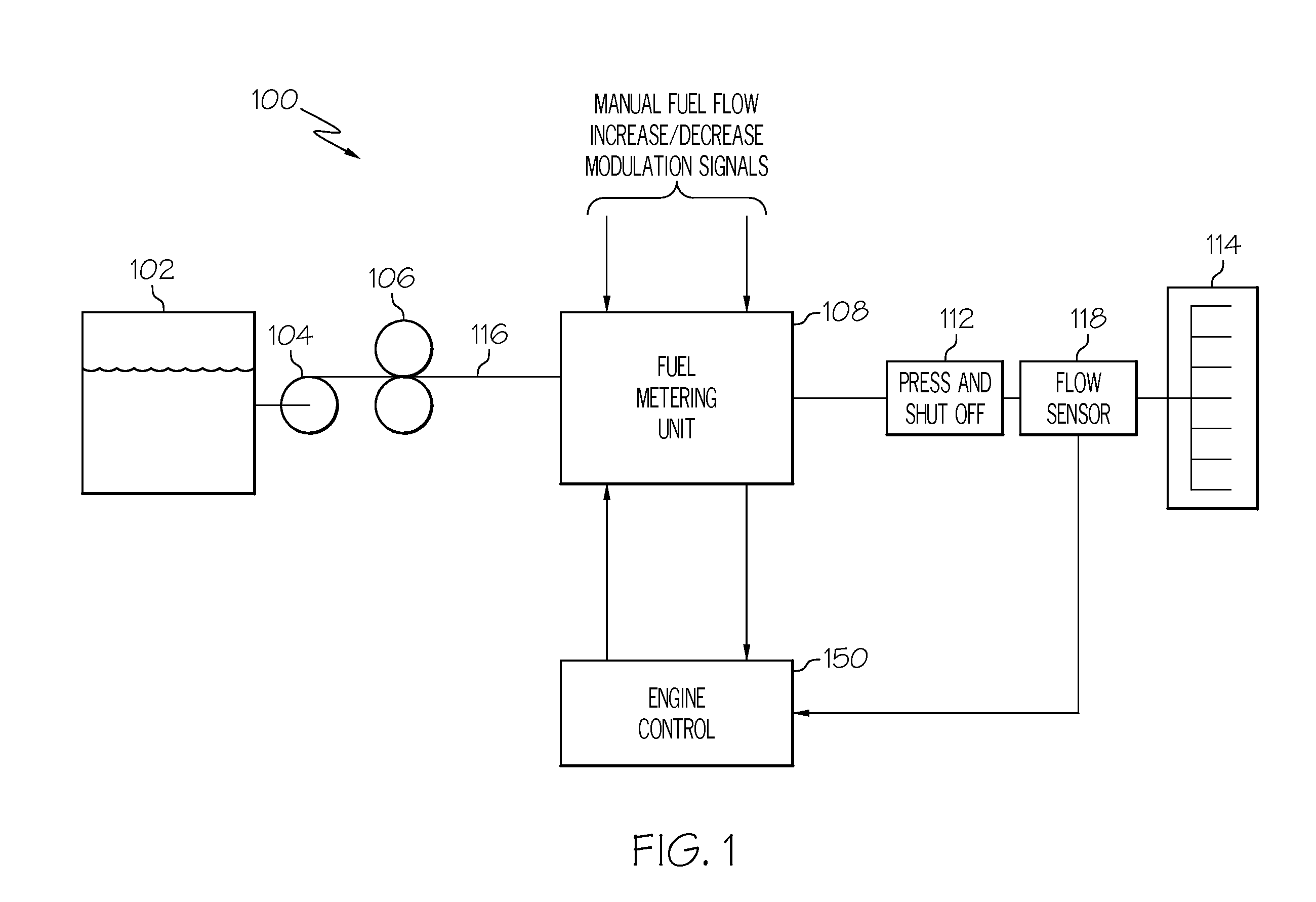
[0014]A simplified schematic diagram of one embodiment of a fuel delivery and control system for a gas turbine engine, such as a turbofan jet aircraft engine, is depicted in FIG. 1. The system 100 includes a fuel source 102, one or more pumps 104, 106, a fuel metering unit 108, and an engine control 150. The fuel source 102, which is preferably implemented as a tank, stores fuel that is to be supplied to a gas turbine engine combustor 114. A supply line 116 is coupled to the fuel source 102 and, via the just-mentioned pumps 104, 106 and fuel metering unit 108, delivers the fuel to the combustor 114. It is noted that the supply line 116 is, f...


PUM


Abstract

A system allows a user to manually manipulate fuel flow to a gas turbine engine during a loss of power to the fuel supply system fuel metering unit. The fuel metering unit includes a fuel metering valve, a metering valve actuator, a fail-fixed valve, a flow increase valve, and a flow decrease valve. The fuel metering unit is configured such that, upon electrical power interruption to the metering valve actuator, the fail-fixed valve shifts and provides a hydraulic lock on the fuel metering valve, to thereby maintain its position. The flow increase and flow decrease valves are powered from a power source that is independent of that used to power the fuel metering unit and, when appropriately energized will allow movement of the fuel metering valve.

Description

TECHNICAL FIELD[0001]The present invention generally relates to gas turbine engine fuel control and, more particularly, to a back-up control system for a gas turbine engine fuel metering valve.BACKGROUND[0002]Typical gas turbine engine fuel supply systems include a fuel source, such as a fuel tank, and one or more pumps that draw fuel from the fuel tank and deliver pressurized fuel to the fuel manifolds in the engine combustor via a main supply line. The main supply line may include one or more valves in flow series between the pumps and the fuel manifolds. These valves generally include at least a main metering valve and a pressurizing-and-shutoff valve downstream of the main metering valve. In addition to the main supply line, many fuel supply systems may also include a bypass flow line connected upstream of the metering valve that bypasses a portion of the fuel flowing in the main supply line back to the inlet of the one or more pumps, via a bypass valve. The position of the bypa...

Claims


Application Information

Patent Timeline
IPC IPC(8): F02M43/02
CPCF02C7/232F02C9/263F23K5/04F23K5/06F23K5/147
Inventor FUTA, JR., PAUL W.LAFFERTY, GREGORY A.
Owner HONEYWELL INT INC
Why Eureka
Try Eureka