Battery charging circuit
- Summary
- Abstract
- Description
- Claims
- Application Information
AI Technical Summary
Benefits of technology
Problems solved by technology
Method used
Image

Examples
Embodiment Construction
)
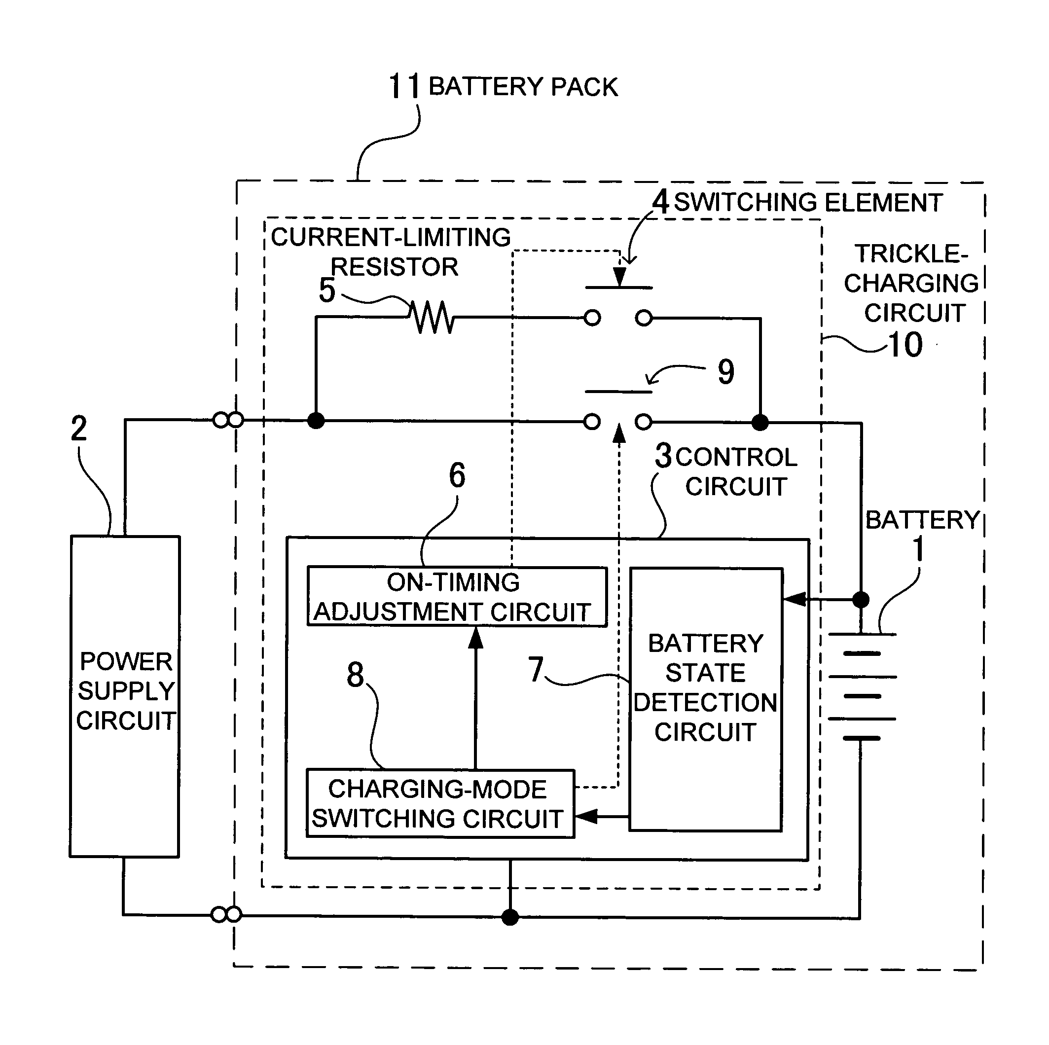
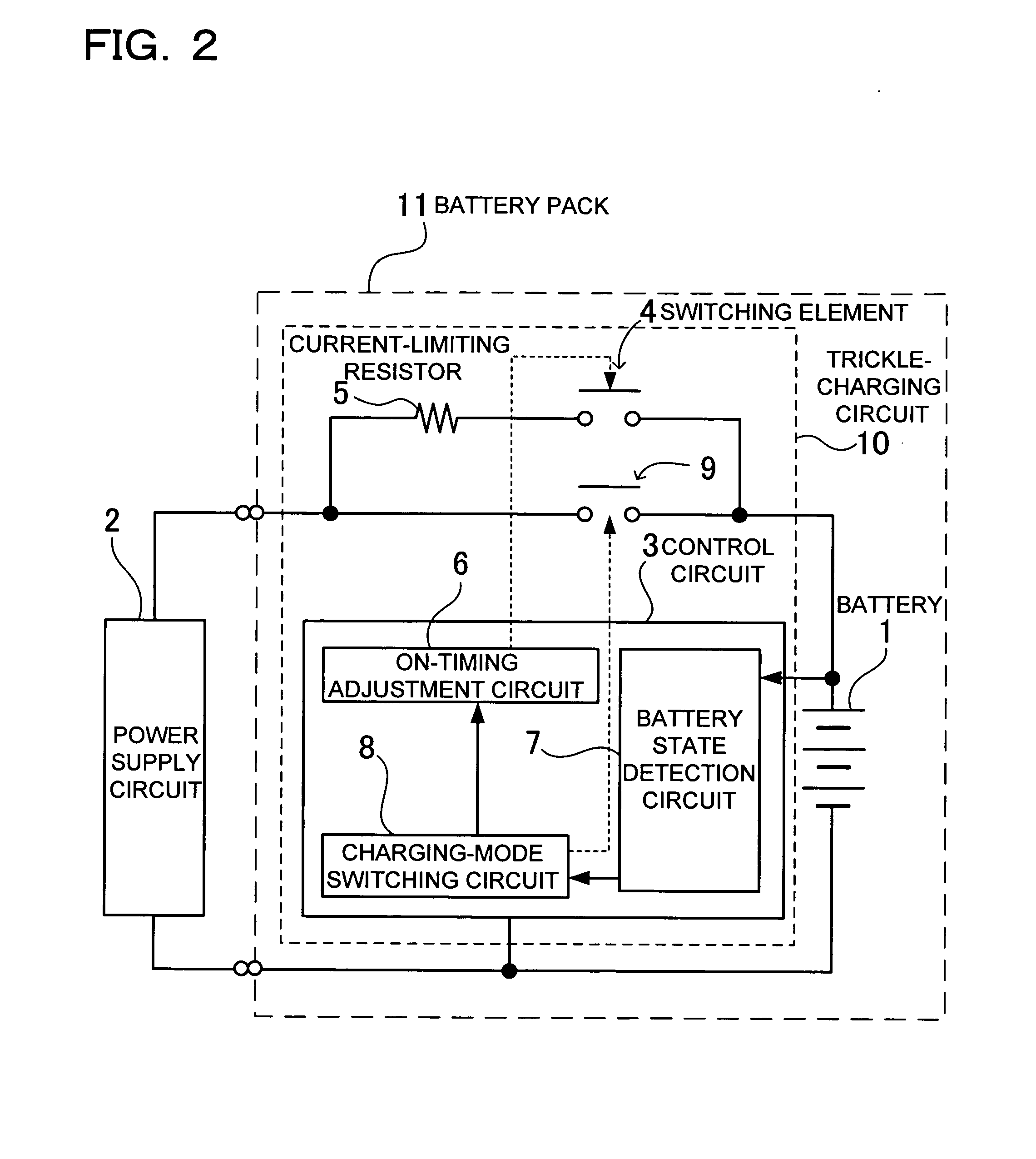
[0020]The charging circuit shown in FIG. 2 includes a power supply circuit 2 connected via a switching element 4 and a current-limiting resistor 5 to a battery 1 to subject the battery 1 to a trickle charge, and a control circuit 3 turning on and off the switching element 4 on a given duty to subject the battery 1 to the trickle charge by means of a pulsed charge. In addition, the charging circuit shown in FIG. 2 is provided with a main switch 9 for charging the battery 1 in a normal charging mode.
[0021]The switching element 4, in a state of subjecting the battery 1 to the trickle charge, is turned on and off by the control circuit 3 and subjects the battery 1 to the pulsed charge. A cycle of the switching element 4 to be turned on or off is set to be for a period of 1 sec to 10 sec, for example. The duty of turning on and off the switching element 4 serves to specify average time to be involved in subjecting the battery1 to the trickle charge. The average current can be made small...
PUM
 Abstract
Description
Claims
Application Information
PatSnap Eureka turns technology decisions into work you can execute. Powered by our Innovation Knowledge Graph, it runs expert workflows across engineering, life sciences, materials and intellectual property. Get your review-ready output in minutes.


