Split power supply circuit for LCD TV

a technology of power supply circuit and lcd tv, which is applied in the field of split power supply circuit for lcd tv, can solve the problems of low circuit efficiency, increased cost of components and circuits, and large noise, and achieves enhanced overall efficiency, simplified conversion among circuit modules, and enhanced flexibility in selection

Inactive Publication Date: 2008-12-04
GETAC TECH CORP
View PDF4 Cites 19 Cited by
  • Summary
  • Abstract
  • Description
  • Claims
  • Application Information

AI Technical Summary

Benefits of technology

[0010]Thus, in view of the problems associated with the conventional LCD TV power supply circuit and further due to the fact that the state-of-art technology is insufficient to overcome such problems, an objective of the present invention is to an improvement of an LCD TV power supply circuit, which is aimed to increase the overall circuit efficiency of the LCD TV power supply circuit.
[0011]Another objective of the present invention is to provide a LCD TV power supply circuit that has a reduced power requirement for circuit modules thereof so that the circuit modules that constitute the power supply circuit can be of enhanced flexibility of selection of the components thereof.
[0014]As to the power requirement for the circuit modules, the present invention provides the LCD TV with enhanced flexibility in selection of the power for circuit modules of the power supply circuit. In other words, the present invention simplifies the conversion among circuit modules for the power supply circuit provided in accordance with the present invention so that overall efficiency is enhanced and costs are reduced.

Problems solved by technology

This makes certain problems, including low circuit efficiency, large noise, and increased costs for components and circuits.
Besides the drawbacks associated with the individual circuit efficiency of each circuit module and the overall circuit efficiency, there are also problems associated with the selection of the components / circuits due to the limitation of power requirement.
The above description shows that the conventional LCD TV power supply circuit suffers problems of low overall efficiency and limitation in selection of power of circuit module.
This is not easy to be done with the state-of-art technology.

Method used


Image

  • Split power supply circuit for LCD TV
  • Split power supply circuit for LCD TV
  • Split power supply circuit for LCD TV

Examples


Embodiment Construction

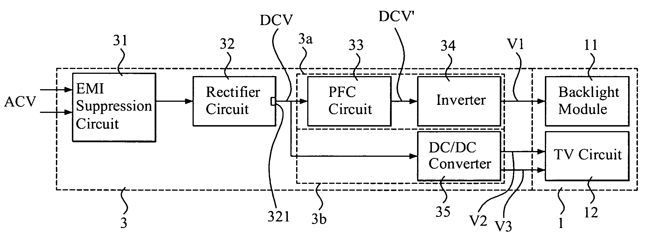
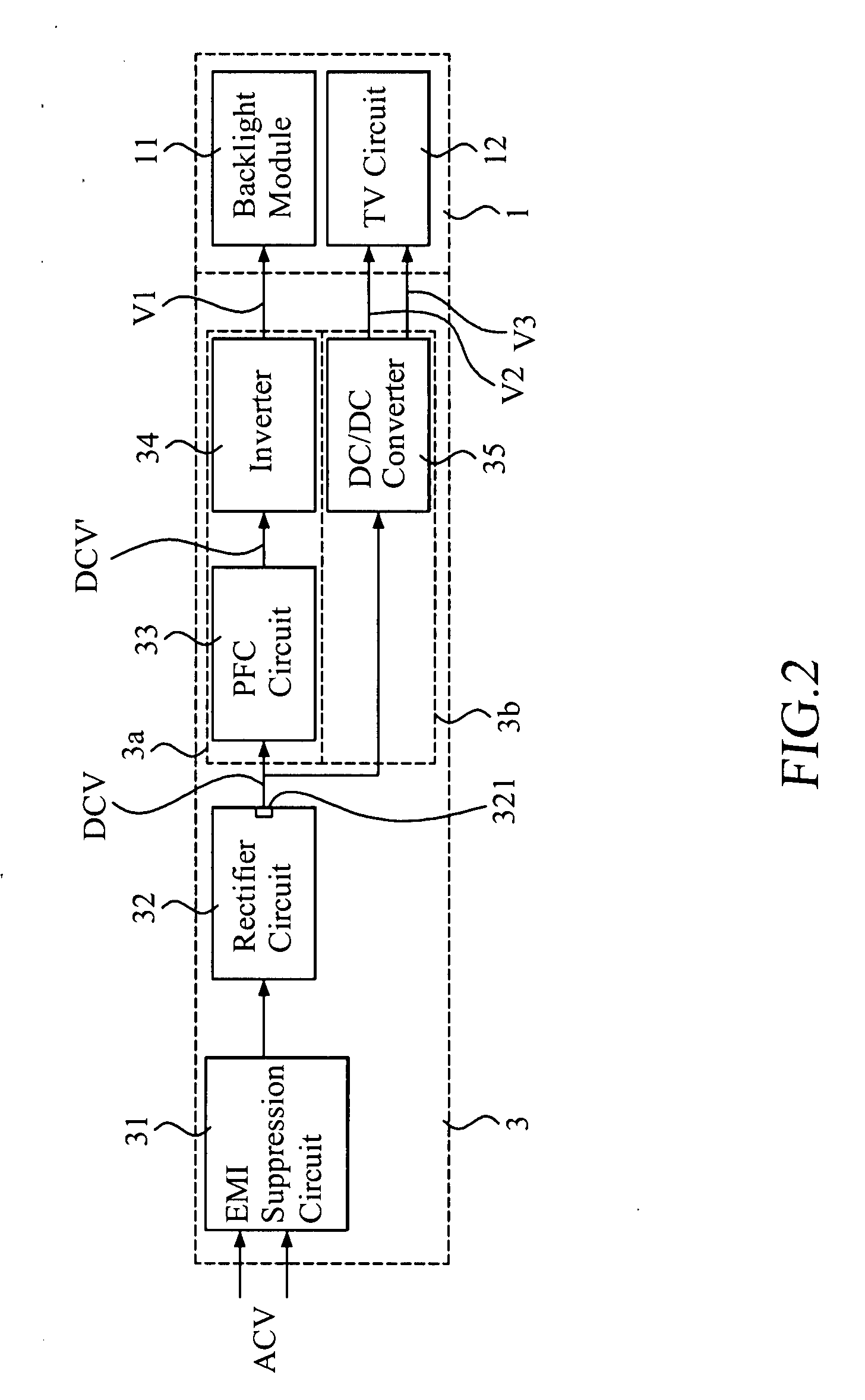
[0019]With reference to the drawings and in particular to FIG. 2, which shows a split power supply circuit, generally designated with reference numeral 3, constructed in accordance with a first embodiment of the present invention, which is provided for powering a liquid crystal display (LCD) television set (TV), the split power supply circuit of the present invention comprises an electromagnetic interference (EMI) suppression circuit 31 and a rectifier circuit 32. The rectifier circuit 32 is connected through the EMI suppression circuit 31 to an alternating current (AC) power source ACV to receive an AC power from the power source ACV and converts the AC power into a direct current (DC) power source (DCV). The DC power is supplied through a DC output terminal 321.

[0020]In accordance with the present invention, the power supply circuit is divided into two power supply sub-circuits. In other words, the power supply circuit 3 includes a backlight module power supply sub-circuit 3a and ...


PUM


Abstract

A liquid crystal display (LCD) television (TV) power supply circuit is split into a backlight module power supply sub-circuit and a TV circuit power supply sub-circuit, wherein the backlight module power supply sub-circuit supplies an operation voltage to a backlight module of the LCD TV and the TV circuit power supply sub-circuit supplies plural operation voltages for a TV circuit of the LCD TV. The backlight module power supply sub-circuit includes a power factor correction circuit and an inverter, and the TV circuit power supply sub-circuit includes a DC / DC converter. The backlight module power supply sub-circuit and the TV circuit power supply sub-circuit may share a common rectifier circuit or they can be provided with direct current powers by respective rectifiers.

Description

FIELD OF THE INVENTION[0001]The present invention relates to a power supply circuit for a liquid crystal display (LCD) television (TV) set, and in particular to split power supply circuit for the LCD TV containing a backlight module power supply sub-circuit and a TV circuit power supply sub-circuit that are separated from each other.BACKGROUND OF THE INVENTION[0002]Liquid crystal display (LCD) television (TV) set is fast popularized due to small thickness, light weight, and reduced power consumption. Thus, the traditional CRT TV sets are gradually replaced by the LCD TV sets.[0003]In the circuit architecture of the LCD TV, a backlight module and a TV circuit are included. The backlight module functions to provide backlighting to the LCD panel. As to the supply of power for the LCD TV, the TV itself requires an operation voltage supplied from a power source to maintain the operation of the TV set. Thus, the power source must be configured to provide both an operation voltage for the ...

Claims


Application Information

Patent Timeline
Patent Type & Authority Applications(United States)
IPC IPC(8): G09G3/36
CPCG09G3/3406G09G2330/021G09G2330/06H04N5/63
Inventor HSIUNG, TA-SUNG
Owner GETAC TECH CORP
Why Eureka
Try Eureka