Optical sheet and display unit using the same

a technology of optical sheets and display units, applied in the direction of optical/shielding arrangements, instruments, gas discharge vessels/containers, etc., can solve the problems of optical sheets increasing their costs, affecting the appearance of visual noise, and affecting the appearance of moiré, so as to reduce the moiré, reduce the interference fringe, and facilitate the configuration

Inactive Publication Date: 2008-12-04
HITACHI CONSUMER ELECTRONICS CORP
View PDF15 Cites 28 Cited by
  • Summary
  • Abstract
  • Description
  • Claims
  • Application Information

AI Technical Summary

Benefits of technology

[0012]According to the present invention, the moiré can be reduced by a convenient configuration. Thus, the present invention can eliminate the necessity of using a diffusion film for reducing the moiré as used in the conventional technology, thereby it is possible to restrain increasing of its cost, and to reduce the moiré.

Problems solved by technology

The ambient light having the above-mentioned reflection pattern, which is reflected upon the display panel and is again incident upon the optical sheet, interferes with the original pattern defined by the light transmitting portions and the light absorbing portions, causing moiré (interference fringes).
The moiré is superposed optically with a displayed image, possibly resulting in occurrence of visual noise.
However, the above-mentioned display panels would inevitably cause the optical sheets to increase its costs, and as a result, display units incorporating this optical sheet increase their costs.

Method used


Image

  • Optical sheet and display unit using the same
  • Optical sheet and display unit using the same
  • Optical sheet and display unit using the same

Examples


embodiment 1

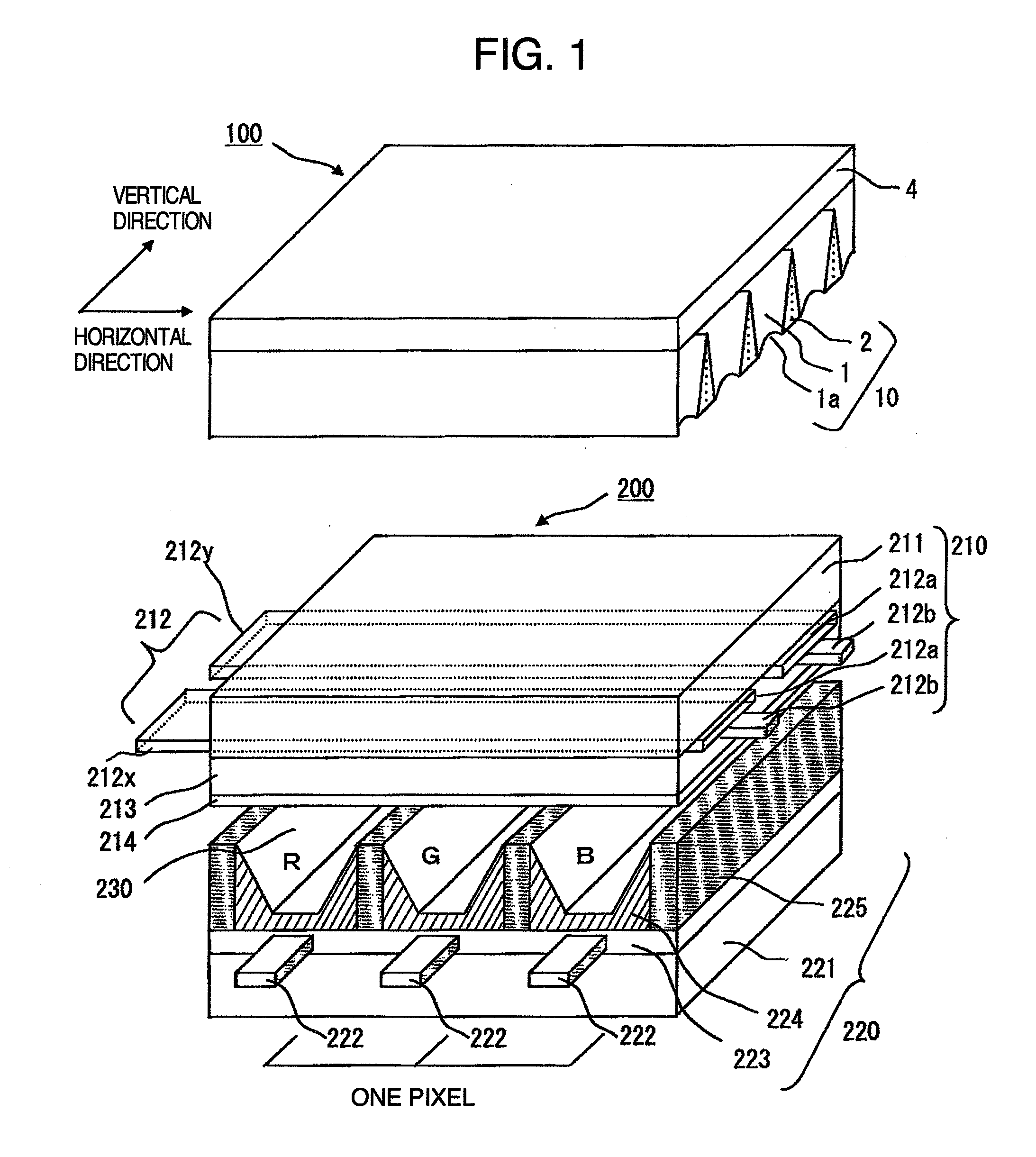
[0022]At first, with references to FIGS. 1, 2 and 3, explanation will be made of a first embodiment of the present invention.

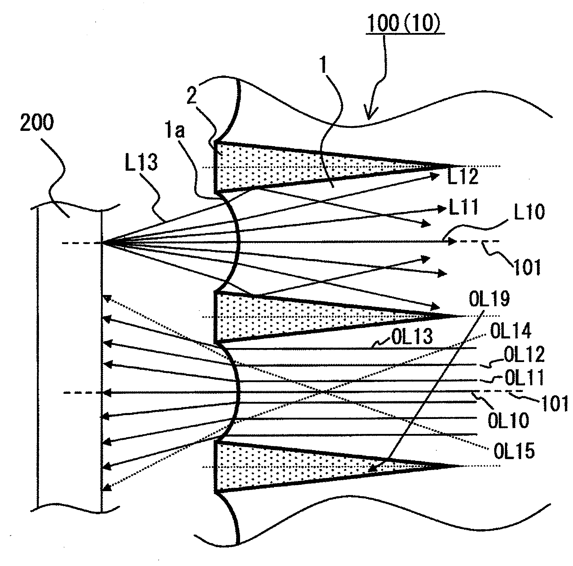
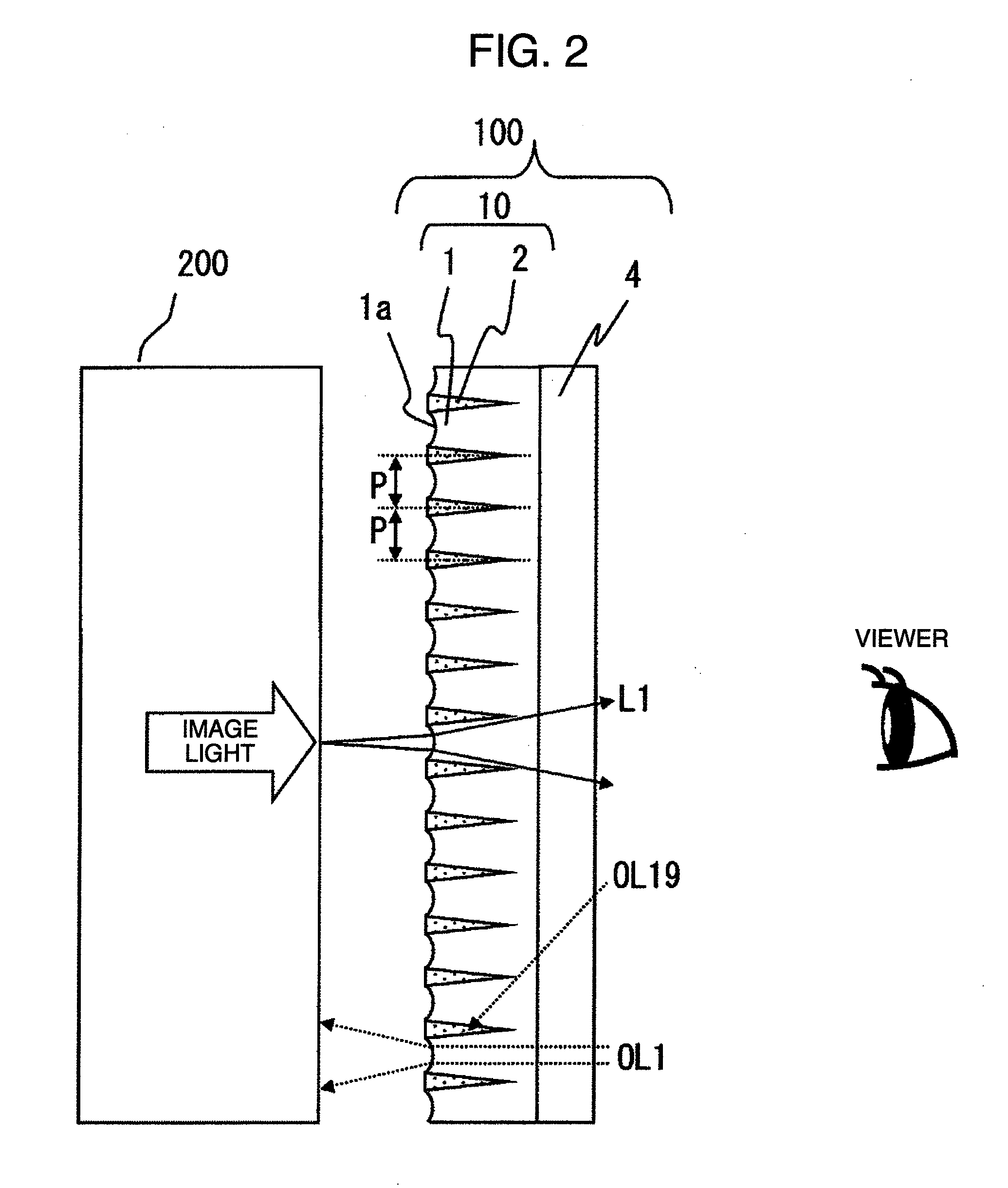
[0023]FIG. 1 is a perspective view illustrating an essential part of a display unit incorporating an optical sheet according to the present invention. It is noted that that the optical sheet in this embodiment is provided in order to enhance, in particular, the contrast of the display unit, and accordingly, this optical sheet will be hereinbelow referred to as “contrast enhancing sheet”. FIG. 2 is a schematic sectional view illustrating the contrast enhancing sheet in this embodiment, and FIG. 3 is an enlarged view illustrating the essential part of the contrast enhancing sheet shown in FIG. 3.

[0024]As to a display unit incorporating the contrast enhancing sheet in this embodiment, there may be exemplified a display unit incorporating a display panel (the so-called flat type display panel) in which pixels for displaying an image are two-dimensionally arrayed, ...

embodiment 2

[0064]Explanation has been made of the embodiment 1 in which the sectional shape of the PDP side end part of the light transmitting portion 1 is concave lens-like with respect to the PDP so as to have a diffusion lens function at the interface with respect to the air layer, having a function of a light diffusion element (diffusion lens effect part).

[0065]On the contrary, in the embodiment 2, the sectional shape of the PDP side end part of a light transmitting portion 1 is set to be convex lens-like so as to form a light diffusion element which is convex toward the PDP. The thus formed convex lens can have a light converging function at the interface thereof with respect to the air layer in order to diffuse the light.

[0066]FIG. 5 is a schematic sectional view which shows a contrast enhancing sheet in this embodiment, and FIG. 6 is an enlarged view illustrating an essential part of the contrast enhancing sheet in this embodiment.

[0067]As shown in FIG. 5, the contrast enhancing sheet 1...

embodiment 3

[0079]Referring to FIG. 7, explanation will be made of an embodiment 3 in which a scattering part 1Ba having a light scattering pattern is formed as a light diffusion element at the PDP side end of the light transmitting portion, instead of the concave lens-like shape part in the embodiment 1, or instead of the convex lens-like shape part in the embodiment 2.

[0080]FIG. 7 is an enlarge view which shows an essential part of the contrast enhancing sheet in this embodiment. It is noted in this figure that the emergent side base layer 4 is not shown for the sake of brevity for illustration.

[0081]As clearly understood from FIG. 7, the contrast enhancing sheet 100B in this embodiment is composed of a contrast enhancing layer 10B and an emergent side base layer 4 in the mentioned order from the PDP 200 side, similar to the embodiment 1 or 2. The contrast enhancing layer 10B are composed of light transmitting portions 1B made of a light transmissible material having a refractive index N1, an...


PUM

PropertyMeasurementUnit
refractive indicesaaaaaaaaaa
shapeaaaaaaaaaa
reflectionaaaaaaaaaa

Abstract

Provided is a contrast enhancing sheet having an excellent bright room contrast function and laid on the screen of a display unit, comprising a plurality of light transmitting portions each having a trapezoid-like sectional shape in a predetermined direction, and a plurality of light absorbing portions each having a wedge-like sectional shape, the top side of the trapezoid-like sectional shape of the light transmitting portion being adjacent to the bottom side of the wedge-like sectional shape of the light absorbing portion, wherein a light diffusion means is provided at the top side of the trapezoid-like sectional shape of the light transmitting portion.

Description

INCORPORATION BY REFERENCE[0001]The present application claims priority from Japanese application JP2007-147616 filed on Jun. 4, 2007, the content of which is hereby incorporated by reference into this application.BACKGROUND OF THE INVENTION[0002]The present invention relates to a technology for improving a contrast function and reducing moiré in the so-called flat type display panel (a display panel of, for example, LCD (Liquid Crystal Display), PDP (Plasma Display Panel), FED (Field Emission Display)) in which pixels are arrayed in a matrix state.[0003]A display unit using a flat type display panel is used for a television display unit (TV). Since a TV is often enjoyed in a bright environment, it is necessary to restrain lowering of the contrast of a display panel caused by the reflection of ambient light (for example, indoor lighting) upon the display panel (that is, to aim at enhancing the contrast in a bright room).[0004]There has been known the technology for improving the con...

Claims


Application Information

Patent Timeline
Patent Type & Authority Applications(United States)
IPC IPC(8): G02B5/02G02B5/00G02F1/1335H01J11/44H01J29/89
CPCG02B3/0056G02B5/0215G02B5/0278
Inventor ADACHI, KEIHIRATA, KOJIYATSU, MASAHIKO
Owner HITACHI CONSUMER ELECTRONICS CORP
Why Eureka
Try Eureka