Scanning procedure in wireless lan, station supporting the same, and frame format therefor

a scanning procedure and wireless lan technology, applied in the field of scanning procedures in wireless lans, can solve the problems of non-ap stas that cannot acquire sufficient information on a network from scanning procedures, and have difficulty in selecting suitable aps, etc., and achieve the effect of increasing channel traffi

Inactive Publication Date: 2008-12-04
LG ELECTRONICS INC
View PDF9 Cites 179 Cited by
  • Summary
  • Abstract
  • Description
  • Claims
  • Application Information

AI Technical Summary

Benefits of technology

[0012]In the previous scanning procedures, the overhead of the non-AP STA performing the scanning procedure increases in a hot spot where a lot of APs are disposed in a narrow area, thereby causing an unnecessary channel load due to a lot of signaling. In the hot spot, this is because the number of beacon frames that should be received by the non-AP STA is great or a lot of probe response frames are transmitted in response to the probe request frame, thereby increasing the channel traffics.

Problems solved by technology

In the previous scanning procedures, the overhead of the non-AP STA performing the scanning procedure increases in a hot spot where a lot of APs are disposed in a narrow area, thereby causing an unnecessary channel load due to a lot of signaling.
In the previous scanning procedure, since there is limit on information that can be acquired by a non-AP STA is, the non-AP STA cannot acquire sufficient information on a network from the scanning procedure even if the scan overhead of the non-AP STA increases.
When the information on a network acquired in the scanning procedure is not sufficient, the non-AP STA has difficulty in selecting a suitable AP by means of the scanning procedure.
Particularly, when the previous active scanning procedure is used, the non-AP STA cannot clearly set a characteristic of an IEEE 802.11 WLAN or a non-IEEE 802.11 network to which the access is desired by the non-AP STA in the probe request frame, thereby unnecessarily increasing the number of probe response frames to be received but not to include sufficient information.
However, the non-AP STA could not sufficiently acquire information on the DS or information on the AN by means of the previous scanning procedure.

Method used


Image

  • Scanning procedure in wireless lan, station supporting the same, and frame format therefor
  • Scanning procedure in wireless lan, station supporting the same, and frame format therefor
  • Scanning procedure in wireless lan, station supporting the same, and frame format therefor

Examples


first embodiment

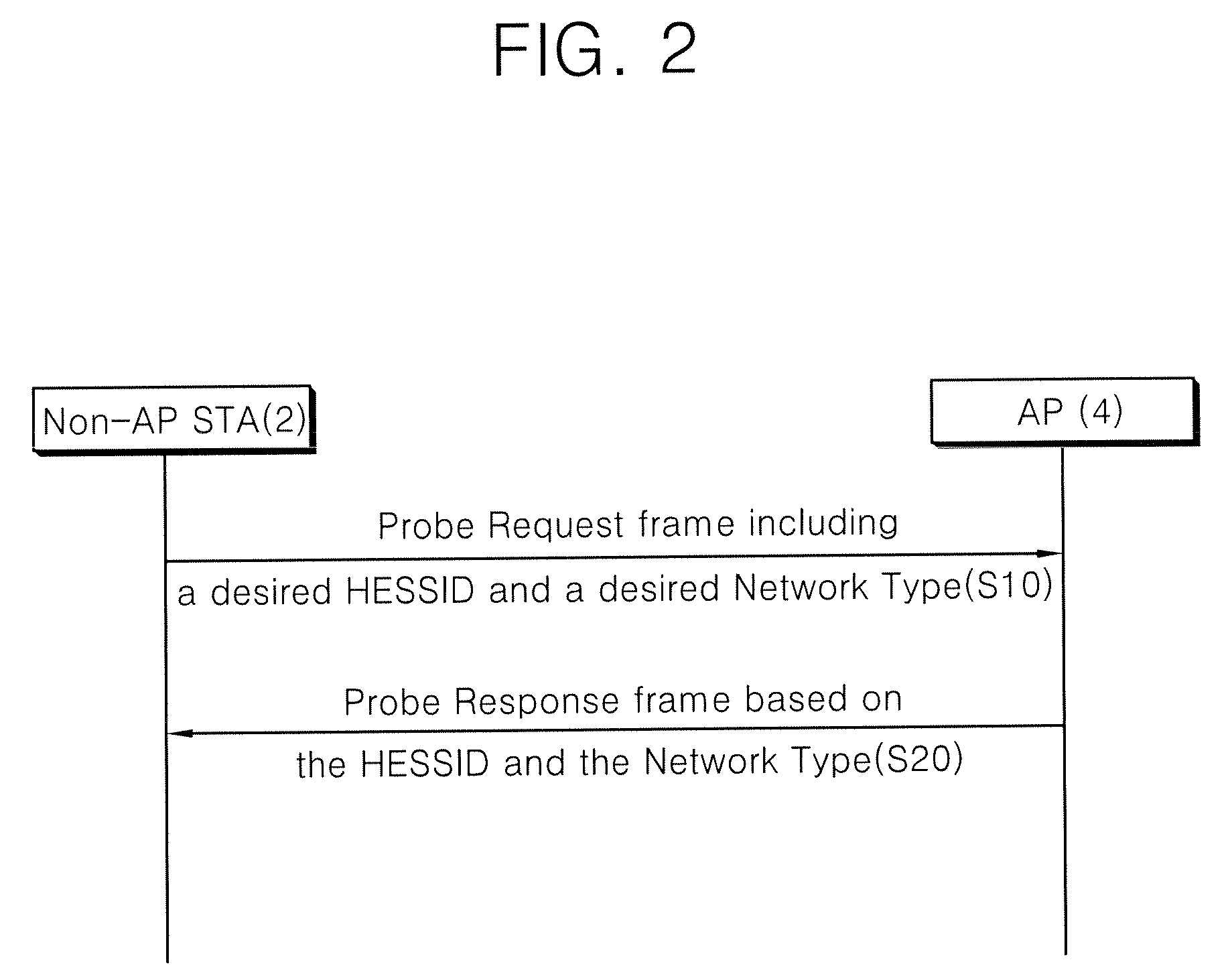
[0055]FIG. 2 is a diagram illustrating a message flow of a scanning procedure in a WLAN according to a first embodiment of the invention. The first embodiment of the invention relates to an active scanning procedure, where a non-AP STA 2 and an AP are stations supporting an interworking service, that is, interworking-capable STAs.

[0056]Referring to FIG. 2, the non-AP STA 2 transmits a probe request frame (S10). The probe request frame can be sent to a broadcast destination address or a unicast destination address. The probe request frame contains HESSID information and network type information desired by the non-AP STA 2 and may further contain desired SSID information and BSSID information.

[0057]FIG. 3 is a block diagram illustrating a format of the probe request frame. Referring to FIG. 3, the probe request frame includes a medium access control (MAC) header, a frame body, and a frame check sequence (FCS). The MAC header includes a frame control field, a duration field, a destinat...

second embodiment

[0077]A second embodiment of the invention also relates to the active scanning procedure in a wireless LAN. As described above, in the active scanning procedure, a non-AP STA transmits a probe request message having a unicast destination address or a broadcast destination address set therein and one or more APs receive the probe request message. The APs having received the probe request message check identification information elements included in the probe request message and then determines whether they should transmit a probe response message. If no relevant information is included in the received identification information, the APs do not transmit the probe response message. On the other hand, when relevant or matched information is included in the received identification information, the APs can transmit the probe response message to reduce a communication channel load in the wireless LAN.

[0078]Here, the identification information includes one or more of a service set ID (SSID)...

third embodiment

[0115]According to a third embodiment of the invention, DS information is added to the beacon frame used in a passive scanning procedure, the probe request frame used in the active scanning procedure, and / or the probe response frame. The DS information is a variety of information on the DS and can include DS type information indicating whether the DS is a wired network or a wireless network such as a mesh network or information on the maximum data transmission rate supported by the DS or the bandwidth used therein. The DS information is contained in one field or an information element (IE) of the beacon frame, the probe request frame, and / or the probe response frame, and a method of expressing the DS information is not limited at all. For example, the DS information may have a format of a bit field indicating whether it is supportable or a format indicating the maximum and / or minimum value supportable.

[0116]FIG. 17 is a block diagram illustrating a format of an interworking informat...


PUM


Abstract

Provided is a scan procedure in a wireless local access network, and station and frame format for the scan procedure. In the scan procedure, a second station receives from a first station a probe request frame which comprises a Homogeneous Extended Service Set Identifier (HESSID) field containing a desired HESSID of the first station and a network type field containing a desired network type of the first station. And, the second station transmits a probe response frame to the first station in response to the probe request frame in case that the HESSID field in the probe request frame is set to a wildcard HESSID or the HESSID of a second station which received the probe request frame, and the network type field in the probe request frame is set to a wildcard network type or the network type of the second station.

Description

CROSS-REFERENCE TO RELATED PATENT APPLICATIONS[0001]This application claims the benefits of Korean Patent Applications Nos. 10-2007-0054034 filed on Jun. 1, 2007 and 10-2008-0023584 filed on Mar. 14, 2008 in the Korean Intellectual Property Office, the disclosures of which are incorporated herein in its entirety by reference.BACKGROUND[0002]1. Field of the Invention[0003]The present invention relates to a wireless local area network (LAN), and more particularly, to a scanning procedure in a wireless LAN, a station supporting the scanning procedure, and a frame format for the scanning procedure.[0004]2. Description of the Related Art[0005]With the development in information communication technology, a variety of wireless communication techniques have been developed. A wireless LAN (WLAN) is a technology permitting wireless access to intra network and / or Internet in specific service areas such as home or companies or air planes by the use of portable terminals such as a personal digit...

Claims


Application Information

Patent Timeline
Patent Type & Authority Applications(United States)
IPC IPC(8): H04Q7/24H04W8/00H04W8/26H04W24/00H04W28/18H04W84/12
CPCH04W8/005H04W8/26H04W24/00H04W28/18H04W84/12H04W48/16H04W88/08
Inventor SEOK, YONG HO
Owner LG ELECTRONICS INC
Why Eureka
Try Eureka