

Direct digital frequency synthesizer with phase selectable interpolator
a digital frequency synthesizer and selectable technology, applied in the direction of synchronising signal speed/phase control, trigometric functions, instruments, etc., can solve the problems of power consumption, complexity and expense of a ddfs generally increasing with an increase in signal quality, and the output frequency of a ddfs generally limited to around 45% of the frequency
- Summary
- Abstract
- Description
- Claims
- Application Information
AI Technical Summary
Benefits of technology
Problems solved by technology
Method used
Image

Examples
Embodiment Construction
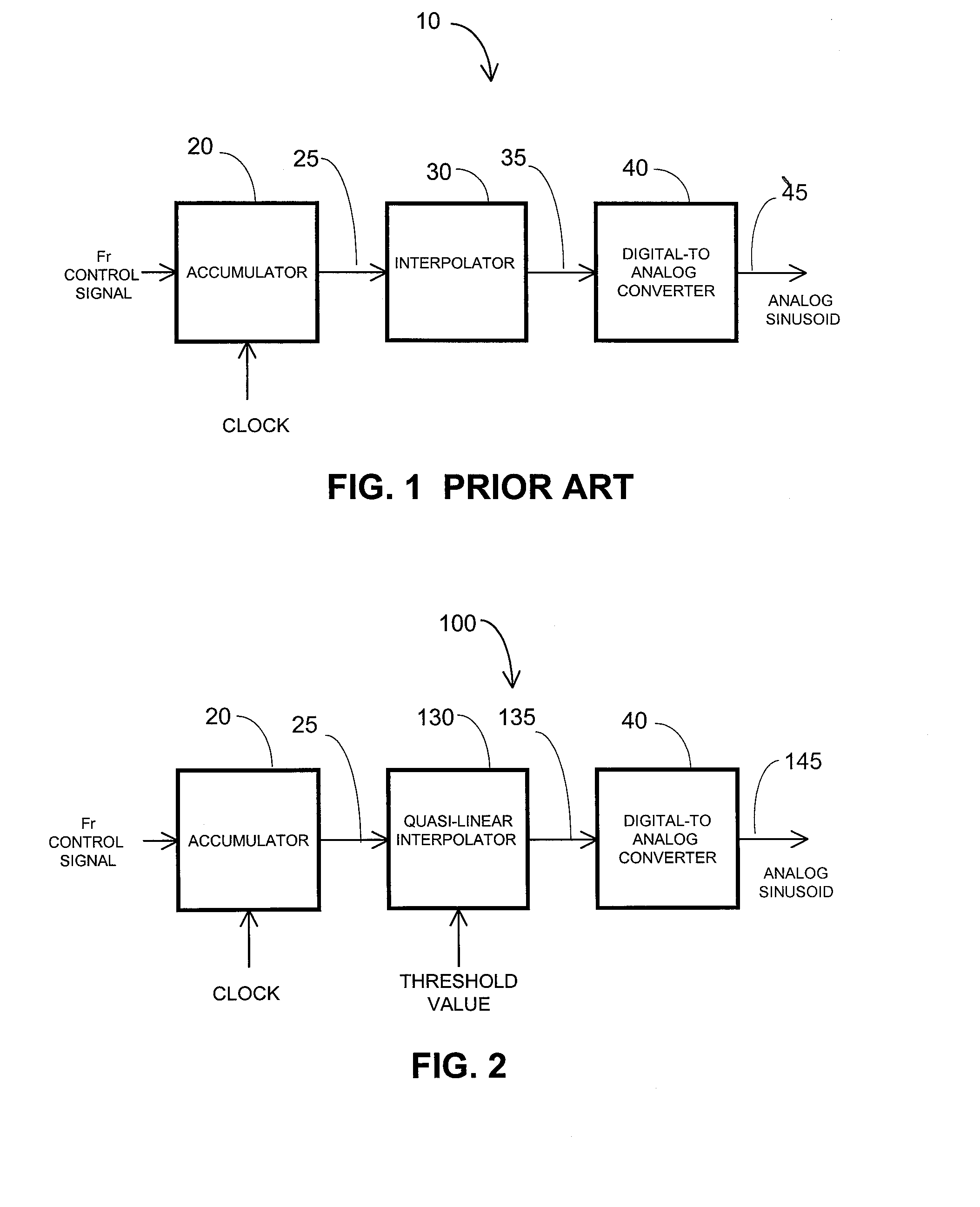
[0021]A conventional direct digital frequency synthesizer (DDFS) 10 is typically comprised of an accumulator 20 and an interpolator 30, as shown in FIG. 1. The accumulator 20 provides a phase signal 25, x, that is sequence of numbers, for processing by interpolator 30. The frequency of the phase signal is dependent on the frequency of the accumulator clock, fclk, and the value of a control signal, Fr. The interpolator 30 responds to the phase signal 25 by generating another sequence of numbers representing a sinusoidal signal 35, S. The quality or purity of the sinusoidal signal 35 is measurable and dependent on a variety of factors as will be seen. When the sinusoidal signal 35 is converted to the continuous time domain by a digital-to-analog converter 40, the sinusoidal signal becomes a continuous time domain sinusoid 45, s(t).
[0022]The phase signal 25 usually has a sawtooth shape, is periodic and has values that span all four quadrants. The output of the interpolator 30 is a sequ...
PUM
 Abstract
Description
Claims
Application Information