
Blasting Device for Premixed Abrasive Slurry Jet

a technology of abrasive slurry and a blasting device, which is applied in the direction of grinding/polishing apparatus, rotor blades, manufacturing tools, etc., can solve the problems of two sealed cavities that lose the seal and then do not work, short life, and difficult maintenance, so as to reduce the cost of production and reduce the friction between the bladder and the body. , the effect of very little friction

Inactive Publication Date: 2008-12-04
ZHOU ZHENGCAI
View PDF22 Cites 10 Cited by
  • Summary
  • Abstract
  • Description
  • Claims
  • Application Information

AI Technical Summary

Benefits of technology

[0007]One object of the present disclosure is to provide a kind of blasting device for producing a premixed abrasive slurry jet to reduce the abrasion.
[0008]Another object of the present disclosure is to provide a kind of blasting device for producing a premixed abrasive slurry jet which has advantages in extended life, easy maintenance and low cost.
[0016]According to the premixed abrasive slurry jet provided by present disclosure, the original piston installed in the cylinder block has been replaced by a bladder. The friction between bladder and body becomes very little, as the slurry is ejected from the nozzle by utilizing the transformation of the bladder. So the life of the blasting device becomes longer. Furthermore, if the bladder becomes broken from use for a long time, it can be easily changed. It is not necessary to change the whole cylinder. So the cost of production is reduced.

Problems solved by technology

Such abrasion makes the originally two sealed cavities to lose the seal and then does not work any more.
Therefore, the conventional hydraulic cylinder has some disadvantage, such as short life, difficult maintenance and high cost.

Method used


Image

  • Blasting Device for Premixed Abrasive Slurry Jet
  • Blasting Device for Premixed Abrasive Slurry Jet
  • Blasting Device for Premixed Abrasive Slurry Jet

Examples


Embodiment Construction

[0020]Preferred exemplary embodiments of the disclosure are depicted in the drawings and explained in greater detail in the following description, where the same reference numerals refer to the same or similar or functionally identical parts.

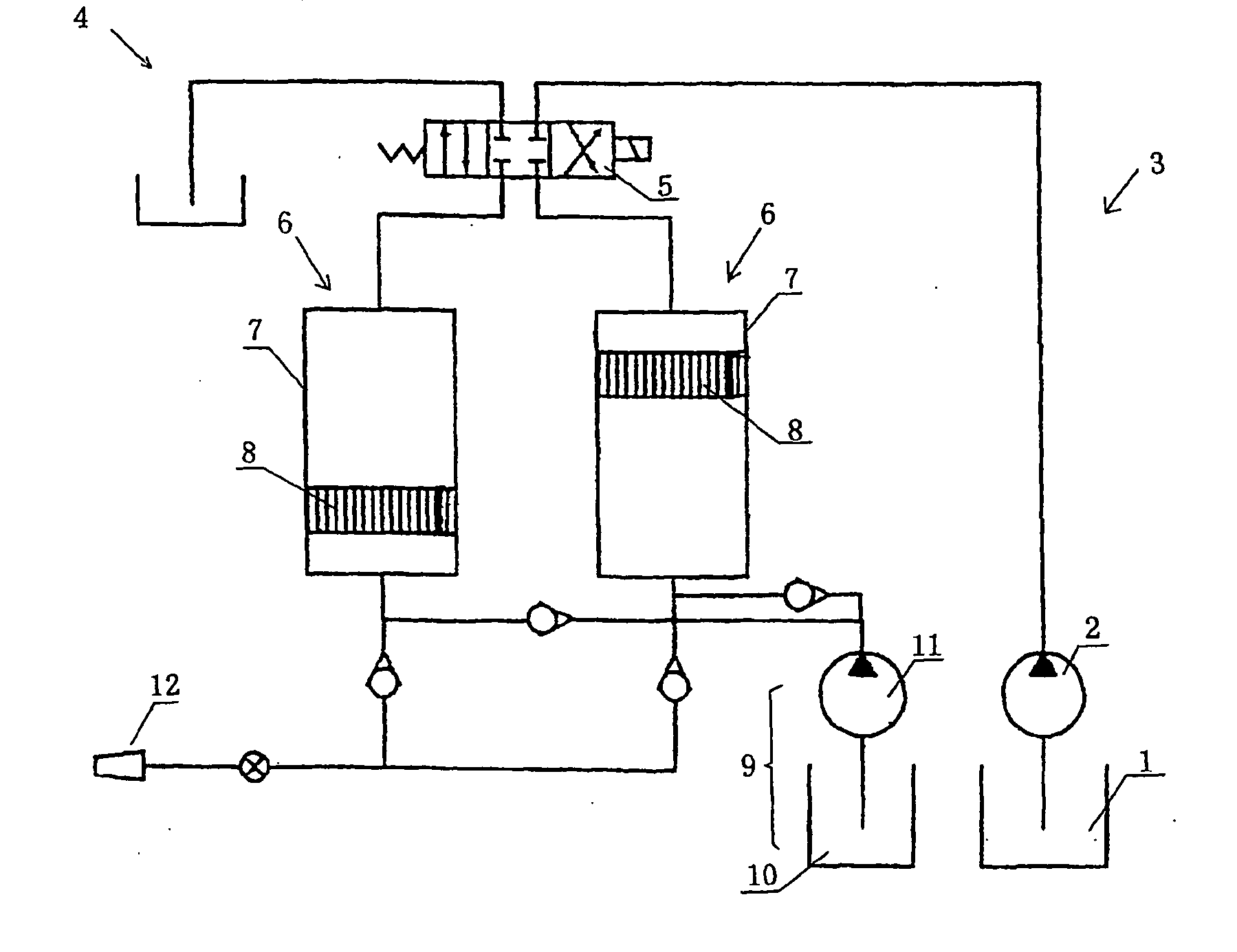
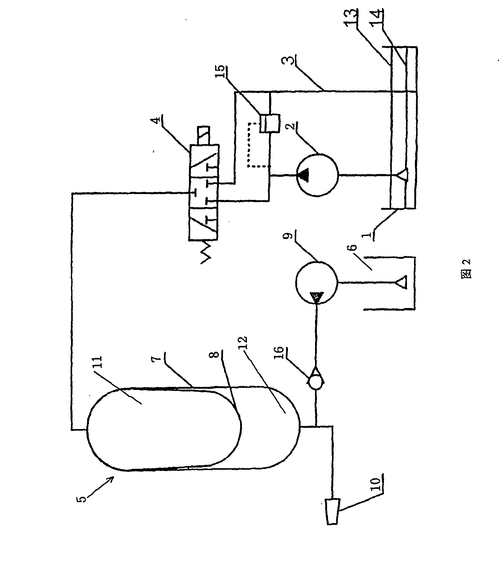
[0021]As shown in FIG. 2, the schematic view of the blasting device for producing a premixed abrasive slurry jet provided by the present disclosure, the blasting device comprises a hydraulic oil tank 1, a high pressure pump 2 connected to the hydraulic oil tank, a oil return pipe 3 connected to the hydraulic oil tank, a sensor 13 for high level at the hydraulic oil tank 1, a sensor 14 for lower level at the hydraulic oil tank 1; a electromagnetic change-over valve 4, a hydraulic cylinder 5. As shown in the FIG. 3, the hydraulic cylinder 5 consists of cylinder block 7 which is made of the stainless steel and bladder 8 which is made of the nitrile rubber. The bladder 8 divides the cylinder block into the hydraulic oil side 11 and the slurry side 1...


PUM


Abstract

The present invention relates to a blasting device for premixed abrasive slurry jet. The device comprise a cylinder, in which defines a hydraulic oil side and a slurry side separated from each other hermetically, and the hydraulic oil side and the slurry side have ports for oil or slurry entry in and out respectively; hydraulic medium feeding system which is connected to the port of the cylinder for oil entry in and out through oil pipe; slurry jet system which is connected to the port of the cylinder for slurry entry in and out through slurry pipe; said cylinder has a sealed bladder to separate the hydraulic oil side and the slurry side. Friction between bladder and body become very little, as the slurry is ejected from the nozzle by utilizing the transformation of the bladder. So service life of the blasting device becomes longer. Furthermore, if the bladder mangles due to wear for use a long time, bladder can be renewed only. It is not necessary to renew the whole cylinder. So the cost of production cuts down.

Description

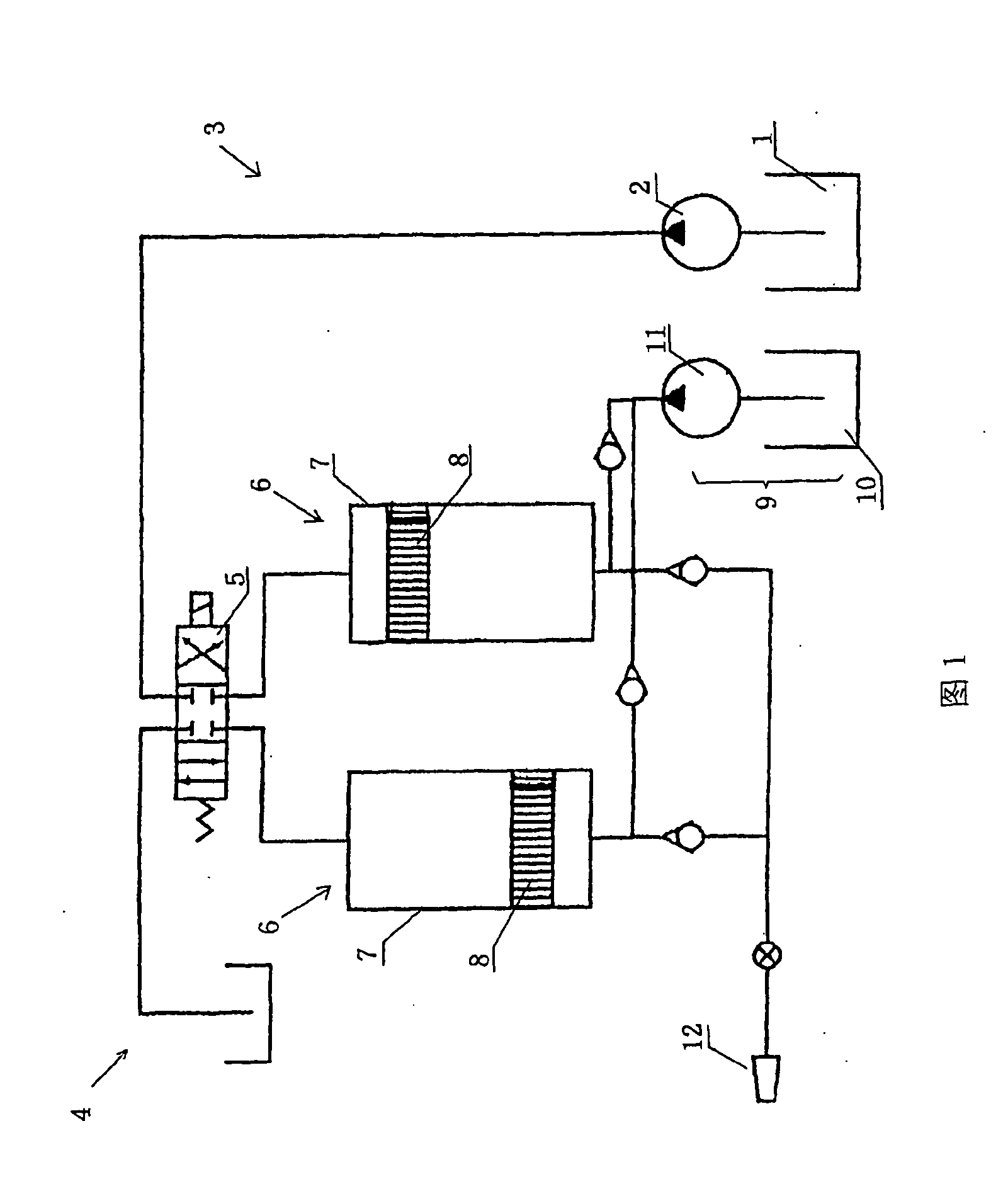
BACKGROUND[0001]1. Field of the Disclosure[0002]This disclosure relates to a blasting device for producing a premixed abrasive slurry jet used for cutting the material in the field of high pressure water jet, especially a kind of blasting device for producing premixed abrasive slurry jets.[0003]2. Discussion of the Background Art[0004]At present, in the case of cutting some hard material, the predominant approach is to depend on the high pressure to drive the slurry carrying the mixture of water and sand in the cutting device to eject at a high speed, which would realize the cutting intention.[0005]The conventional cutting device, e.g. the blasting device for producing a premixed abrasive slurry jet disclosed in the section 10.2.3 of the publication of High Pressure Water Jet Technology and Its Application (Shengxiong Xue et al., High Pressure Water Jet Technology and Its Application, China Machine Press, 1998.8). As shown in the FIG. 1, the device comprises hydraulic oil tank 1, hi...

Claims


Application Information

Patent Timeline
Patent Type & Authority Applications(United States)
IPC IPC(8): B24C5/06
CPCB24B57/02B24C5/00B24C7/0007
Inventor ZHOU, ZHENGCAI
Owner ZHOU ZHENGCAI
Learn More