
Aligning Radio Base Station Node Transmission Timing on Multiple Transmit Paths

a radio base station and multiple transmit path technology, applied in the field of wireless telecommunications, can solve the problems of significant constraints imposed on the operation of the radio base station, difficulties, and the acuteness of delay differences and variations, and achieve the effects of reducing power, satisfactory resolution and/or accuracy, and sufficient resolution and/or accuracy

Active Publication Date: 2008-12-04
TELEFON AB LM ERICSSON (PUBL)
View PDF5 Cites 34 Cited by
  • Summary
  • Abstract
  • Description
  • Claims
  • Application Information

AI Technical Summary

Benefits of technology

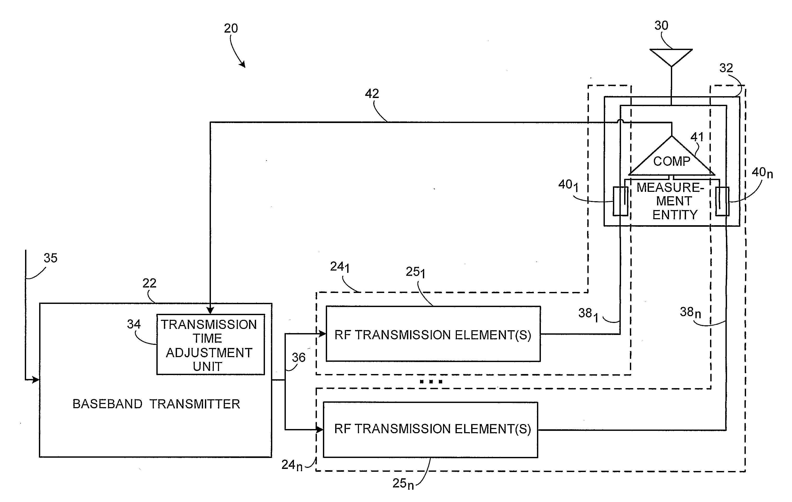
[0023]The test signals of the second example mode can be a sequence of test symbols using a same timing (e.g., chip timing). The I and Q components of each test symbol in a particular transmit path can be chosen as follows: in an ideal environment for each symbol period the combination (addition) of the complex radio signals generated from those I and Q components result in a complex RF signal with amplitude equal to zero (e.g., a lowest power level). Such provides maximum cancellation.

Problems solved by technology

In such cases, and particularly in a WCDMA system, significant constraints are imposed on the operation of the radio base station regarding the allowed timing difference of transmit (TX) transmission on the different transmission paths.
Difficulties arise from various factors or timing uncertainties and / or variations in the radio base station nodes themselves, both in digital components and (perhaps even more) in analog components forming a transmit path up to the antenna.
The problems of delay differences and variations are particularly acute in the case of co-sited radio base stations (occurring, e.g., in GSM and UMTS) where radio frequency (RF) equipment is shared.

Method used


Image

  • Aligning Radio Base Station Node Transmission Timing on Multiple Transmit Paths
  • Aligning Radio Base Station Node Transmission Timing on Multiple Transmit Paths
  • Aligning Radio Base Station Node Transmission Timing on Multiple Transmit Paths

Examples


Embodiment Construction

[0044]In the following description, for purposes of explanation and not limitation, specific details are set forth such as particular architectures, interfaces, techniques, etc. in order to provide a thorough understanding of the present invention. However, it will be apparent to those skilled in the art that the present invention may be practiced in other embodiments that depart from these specific details. In other instances, detailed descriptions of well-known devices, circuits, and methods are omitted so as not to obscure the description of the present invention with unnecessary detail. Moreover, individual function blocks are shown in some of the figures. Those skilled in the art will appreciate that the functions may be implemented using individual hardware circuits, using software functioning in conjunction with a suitably programmed digital microprocessor(s) or general purpose computer(s), either distributed or concentrated, and using an application specific integrated circu...


PUM


Abstract

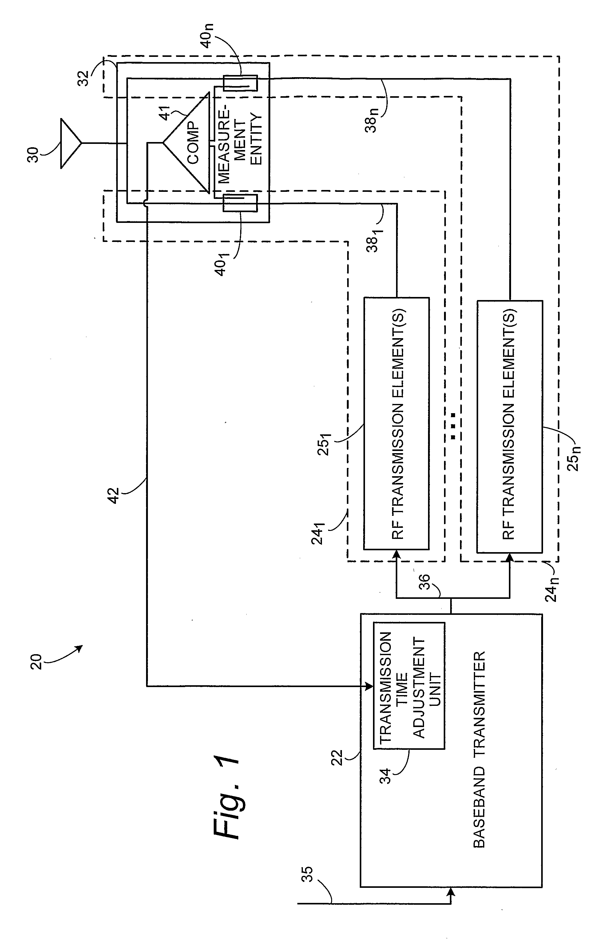
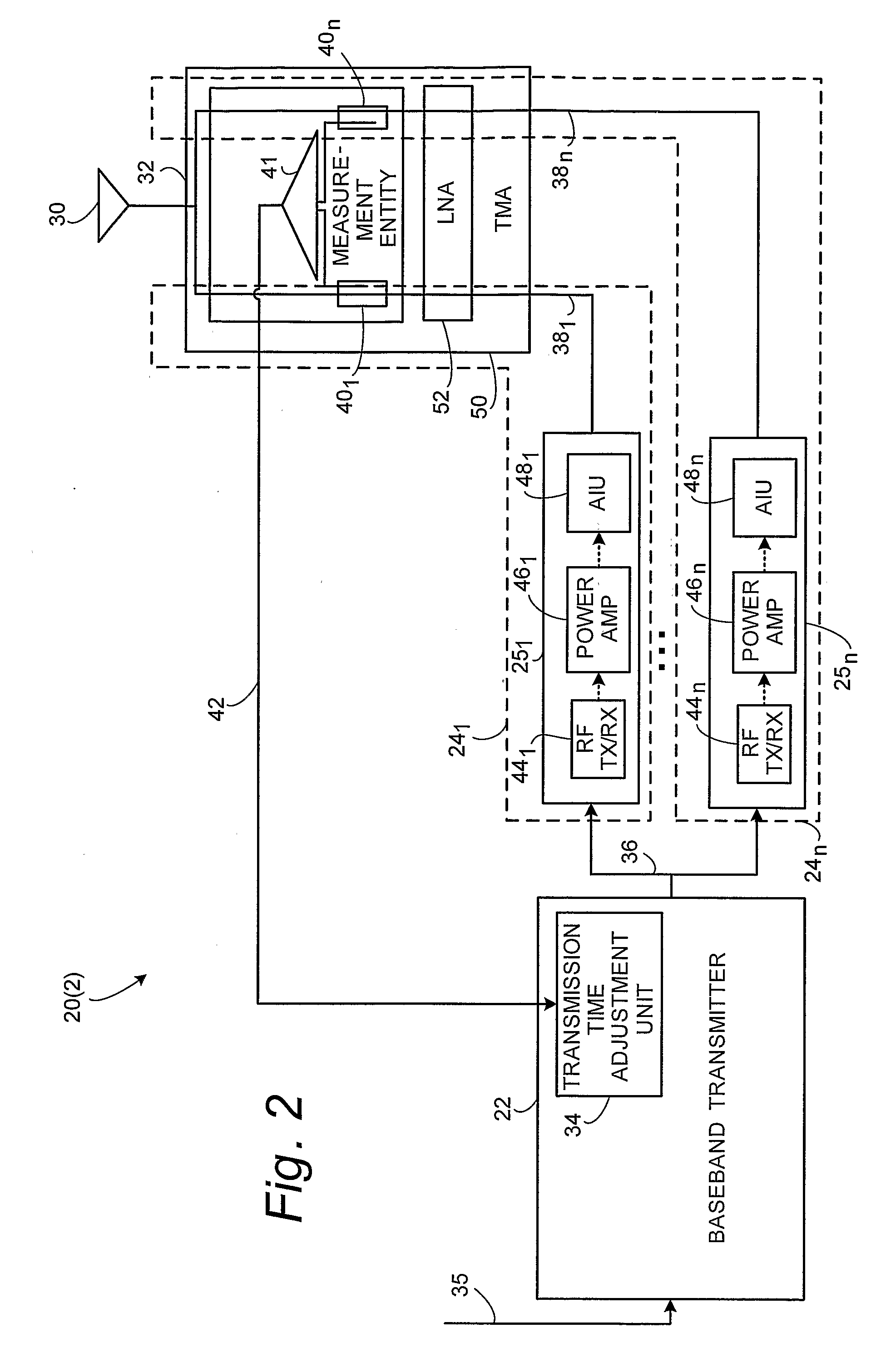
A radio base station node (20) of a telecommunications network comprises a baseband transmitter (22) and plural radio frequency (RF) paths (24) between the baseband transmitter (22) and an antenna system (30). A measurement entity (32) is provided, preferably near the antenna system (30), for making a measurement or comparison of a time of detecting of a power modulation for each of plural RF transmission paths (24), e.g., a time of detecting of a power modulation for a first of the plural RF transmission paths and a time of detection of a power modulation for a second of the plural RF transmission paths. A transmission timing adjustment unit (34) uses the power modulation measurement or comparison for adjusting timing of transmission of signals for the plural RF transmission paths for obtaining a desired time alignment for the plural RF transmission paths.

Description

[0001]This application claims the benefit and priority of U.S. Provisional Patent Application 60 / 585,098, filed Jul. 6, 2004, which is incorporated herein by reference in its entirety.BACKGROUND[0002]1. Field of the Invention[0003]The present invention pertains to wireless telecommunications, and particularly to alignment of plural transmit paths in a radio base station node of a telecommunications system.[0004]2. Related Art and Other Considerations[0005]In a typical cellular radio system, mobile user equipment units (UEs) communicate via a radio access network (RAN) to one or more core networks. The user equipment units (UEs) can be mobile stations such as mobile telephones (“cellular” telephones) and laptops with mobile termination, and thus can be, for example, portable, pocket, hand-held, computer-included, or car-mounted mobile devices which communicate voice and / or data with radio access network.[0006]The radio access network (RAN) covers a geographical area which is divided ...

Claims


Application Information

Patent Timeline
IPC IPC(8): H04B7/00
CPCH04B17/14H04B7/0671
Inventor JECK, MICHAELHILDEBRAND, UWE
Owner TELEFON AB LM ERICSSON (PUBL)
Learn More