System and method for selecting a location for marking placement

a marking placement and location technology, applied in the field of objects marking, can solve the problems of limited marking range, traditional marking system, and effective use of marking on relatively large areas and flat surfaces

Active Publication Date: 2008-12-04
ALIGN TECH
View PDF6 Cites 22 Cited by
  • Summary
  • Abstract
  • Description
  • Claims
  • Application Information

AI Technical Summary

Benefits of technology

[0009]In one aspect of the present invention, a method and system is provided for locating a marking position on one or more selected areas of an item. This aspect includes determining that one or more selected areas of an item has at least a minimum surface area; determining a plurality of height measurements relative to a reference level and locations on each of the one or more selected areas; determining the average of the measured heights for each of the one or more selected areas; calculating the absolute value of the height difference between the average of the measured heights and an optimum height to generate an absolute height value for

Problems solved by technology

Traditional marking systems however, may have limited marking range and can only be used effectively to provide marking on relatively large areas and flat surfaces.
Unfortunately, many surfaces that may require marking are relatively small and uneven.
This is especially true in the medical prosthetics industry, where marking quality may be adversely affected by extreme anatomy.
For example, in the dental appliance manufacturing industry, the marking quality on dent

Method used


Image

  • System and method for selecting a location for marking placement
  • System and method for selecting a location for marking placement
  • System and method for selecting a location for marking placement

Examples


Embodiment Construction

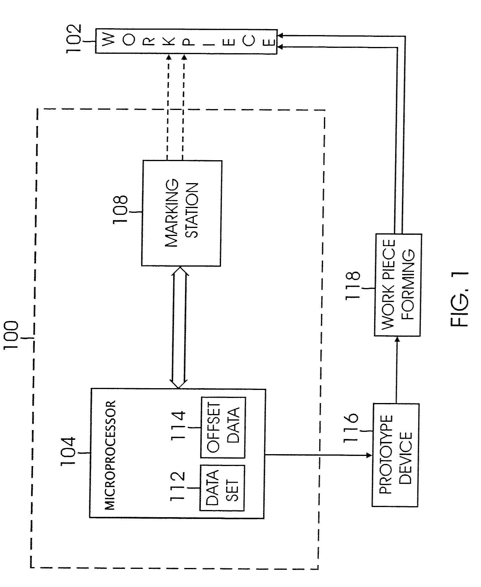
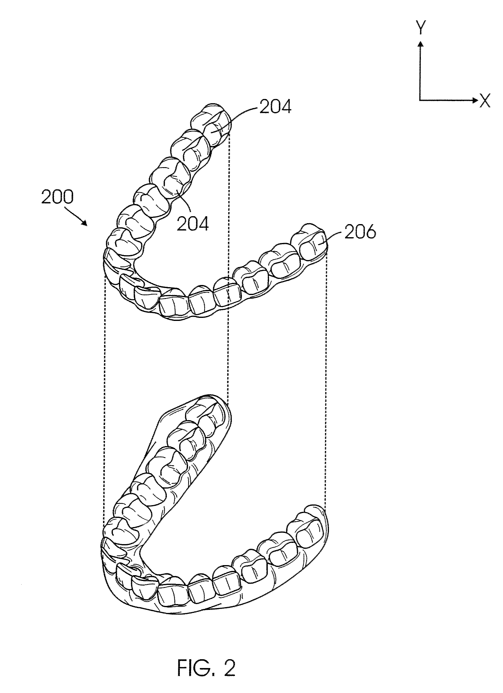
[0023]In the detailed description of the invention that follows the invention is described primarily in the context of a system and associated method for locating, selecting and creating an area suitable for marking on an object, such as on mass produced, customized dental appliances. It should be understood however, that the system and method of the present invention may be employed in the locating, selecting and creating of an area suitable for marking on any of various types of workpieces, having limited marking area and uneven marking surfaces, such as, prosthetic body parts, athletic gear, implantable hearing aids and the like.

[0024]Furthermore, although a marking device described herein in connection with the embodiments of the invention is a laser, it will be apparent that other types of marking devices known in the art, such as ink jet printers, ultrasonic devices, CNC machines, and the like, may be employed in place of, or in conjunction with, the laser. In addition, any nu...


PUM


Abstract

A system and associated method for selecting or creating an area which meets meet a set of marking criteria, for example, corresponding to a minimum surface area; a maximum slope angle; and a minimum deviation from a specified height. A marking station is directed to mark the selected area that meets the marking criteria.

Description

BACKGROUND[0001]1. Field of the Invention[0002]This invention relates to the marking of objects, and more particularly to a system and associated method for selecting a location for marking placement.[0003]2. Related Art[0004]It has become common practice to mark products with labels, identification numbers, and company logos. For example, laser marking (LM) can provide a permanent marking with high contrast that does not wear off or degrade with use. Traditional marking systems however, may have limited marking range and can only be used effectively to provide marking on relatively large areas and flat surfaces.[0005]Unfortunately, many surfaces that may require marking are relatively small and uneven. This is especially true in the medical prosthetics industry, where marking quality may be adversely affected by extreme anatomy. For example, in the dental appliance manufacturing industry, the marking quality on dental aligners may be adversely affected by abnormal dental structures...

Claims


Application Information

Patent Timeline
IPC IPC(8): G01B21/18G03G15/00
CPCA61C7/002A61C7/08B33Y80/00
Inventor CULP, JAMES C.FARREN, CRAIG E.BOROVINSKIH, ARTEMKUO, ERIC
Owner ALIGN TECH
Why Eureka
Try Eureka