Apparatus and method for distinguishing single bit errors in memory modules

a memory module and error correction technology, applied in error detection/correction, instruments, computing, etc., can solve problems such as peripherals, application-specific integrated circuits, and data stored in memory to occasionally have errors,

Inactive Publication Date: 2008-12-04
GLOBALFOUNDRIES INC
View PDF10 Cites 39 Cited by
  • Summary
  • Abstract
  • Description
  • Claims
  • Application Information

AI Technical Summary

Problems solved by technology

It is not uncommon for data stored in memory to occasionally have an error.
This data line error may again be temporary or permanent.
Computer, peripherals, application-specific integrated circuits (“ASICs”), etc. with memory that includes ECC stored with data often count recoverable errors.
A bit error count typically increments slowly for random events caused by temporary errors during normal operation, but then may increment more quickly as memory or a memory controller starts to degrade.
By contrast, a single permanent bit error may increment the bit error count quickly.
This would occur if the single bit permanent error was accessed frequently.
A permanent single bit error condition may generate a lot of errors if the memory address containing the single bit error is accessed frequently.
A bit error count may then increase quickly signaling a problem with the memory.
However, the memory may be functioning correctly even though the single memory cell is incorrect.
In this case the reliability of the memory has been reduced because a second error at the memory address containing the permanent error is not correctable using typical ECC methods.
However, the current state of the art is unable to distinguish between single single permanent errors and single random, temporary errors.
In addition, the current state of the art is unable to distinguish bit line errors and memory module errors from other errors.

Method used


Image

  • Apparatus and method for distinguishing single bit errors in memory modules
  • Apparatus and method for distinguishing single bit errors in memory modules
  • Apparatus and method for distinguishing single bit errors in memory modules

Examples


Embodiment Construction

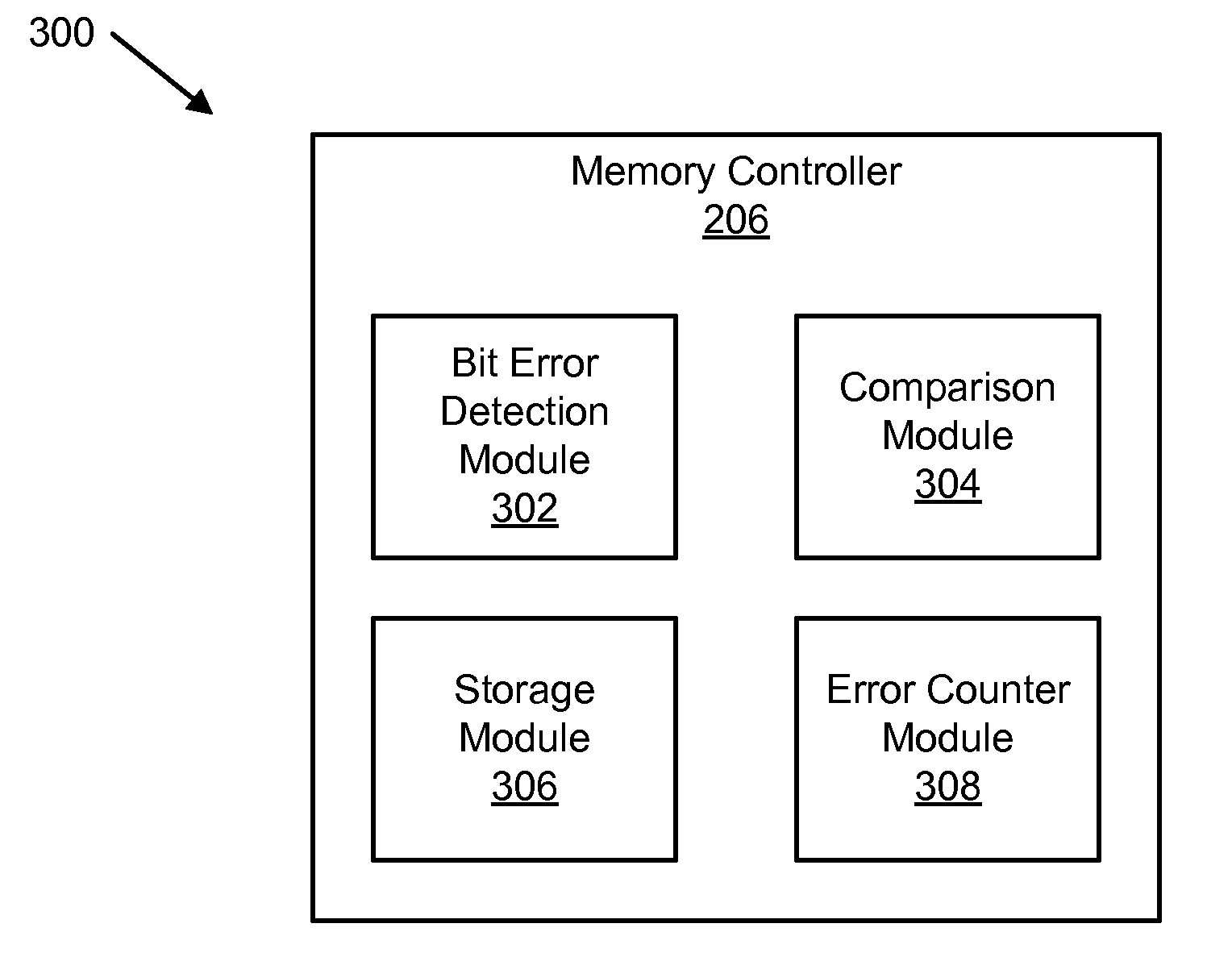
[0051]Many of the functional units described in this specification have been labeled as modules, in order to more particularly emphasize their implementation independence. For example, a module may be implemented as a hardware circuit comprising custom VLSI circuits or gate arrays, off-the-shelf semiconductors such as logic chips, transistors, or other discrete components. A module may also be implemented in programmable hardware devices such as field programmable gate arrays, programmable array logic, programmable logic devices or the like.

[0052]Modules may also be implemented in software for execution by various types of processors. Software modules are stored on a computer readable media, such as memory, disk drives, removable data storage media, and the like. Modules may also comprise hardware and software where the software portion of the module is stored on a computer readable medium. An identified module of executable code may, for instance, comprise one or more physical or l...


PUM


Abstract

An apparatus, system, and method are disclosed for distinguishing correctable bit errors in memory. A bit error detection module detects a correctable bit error in memory. The correctable bit error is correctable using error-correcting code (“ECC”). A comparison module compares an error location indicator with a stored error location indicator. The error location indicator is a location of the correctable bit error. The stored error location indicator includes to at least one previously stored error location indicator of a previously detected correctable bit error. A storage module stores the error location indicator in response to the comparison module determining that the error location indicator differs from a stored error location indicator. A bit error counter module increases a random bit error counter if the comparison module determines that the error location indicator differs from a stored error location indicator and does not increase the random bit error counter otherwise.

Description

RELATED APPLICATIONS [0001]This Application is related to U.S. patent application Ser. No. ______, filed on Jun. 1, 2007, titled APPARATUS AND METHOD FOR DISTINGUISHING TEMPORARY AND PERMANENT ERRORS IN MEMORY MODULES for Carol Spanel, et al., IBM Docket Number SJO920070002US1, which is herein incorporated by reference.BACKGROUND OF THE INVENTION[0002]1. Field of the Invention[0003]This invention relates to error correction in memory and more particularly relates to distinguishing between temporary and permanent bit errors in memory modules.[0004]2. Description of the Related Art[0005]Computer memory is an essential element of any computing system and data integrity is vitally important to prevent computing errors. Computer memory may be static, where data is retained when the computer is not operating, or dynamic, where data is lost when the computer is not operating. Random access memory (“RAM”) is a typical form of dynamic memory that loses its contents when a computer is shut do...

Claims


Application Information

Patent Timeline
Patent Type & Authority Applications(United States)
IPC IPC(8): G11C29/52
CPCG06F11/1012G11C5/04G11C29/44G11C29/52G11C2029/0409G11C2029/0411
Inventor SPANEL, CAROLWALLS, ANDREW DALE
Owner GLOBALFOUNDRIES INC
Why Eureka
Try Eureka