Storage tank for cryogenic liquids

a technology for storage tanks and liquids, applied in the direction of mechanical equipment, vessel construction details, container discharging methods, etc., can solve the problems of significant time needed between and the outer wall, and achieve the effect of saving significant construction tim

Active Publication Date: 2008-12-11
CHICAGO BRIDGE & IRON CO
View PDF13 Cites 45 Cited by
  • Summary
  • Abstract
  • Description
  • Claims
  • Application Information

AI Technical Summary

Benefits of technology

[0010]In this new procedure, a freestanding inner steel liner is erected. The liner is sized and configured to withstand the hydraulic forces of wet concrete as the wall is poured without the need for internal stiffeners in lower portions of the tank. The liner may, for example, have a thickness of more than 8 mm. Without interference from formwork or internal stiffening, construction of a roof may begin inside the liner before the pour of the outer wall is completed, saving significant construction time.
[0011]To help maintain proper positioning of the liner during the pour of the outer concrete wall, lateral tension ties can be connected to an outward surface of the liner and used to help tie the liner to the outer formwork. In some circumstances, it may be beneficial to space these ties more closely together than the ties used in conventional arrangements; for example between ¾ and 1 1 / 2 m apart, instead of more than 2 m apart.

Problems solved by technology

Using the conventional processes, significant time is needed between the start of work on the outer wall and the start of work on the roof.

Method used


Image

  • Storage tank for cryogenic liquids
  • Storage tank for cryogenic liquids
  • Storage tank for cryogenic liquids

Examples


Embodiment Construction

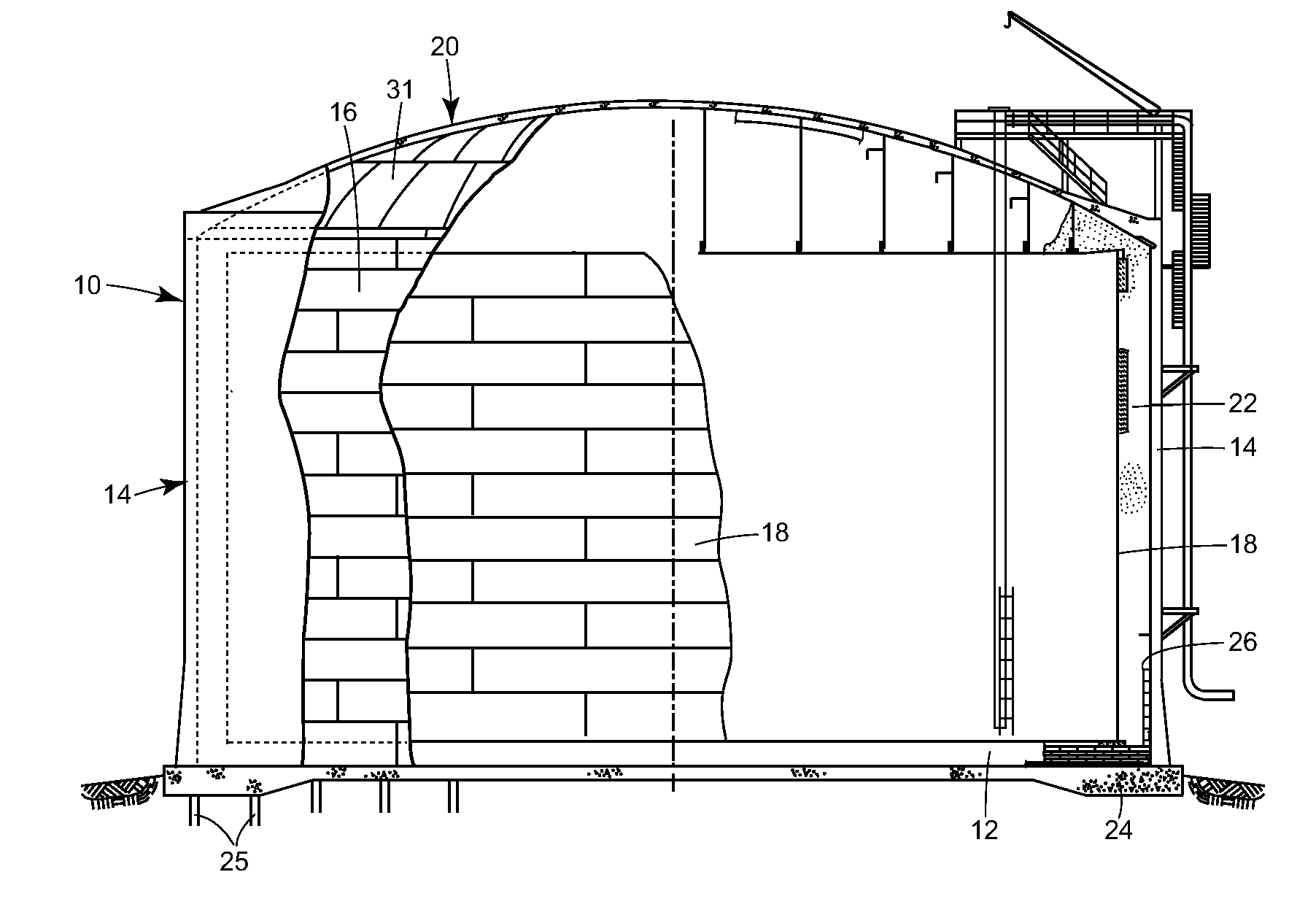
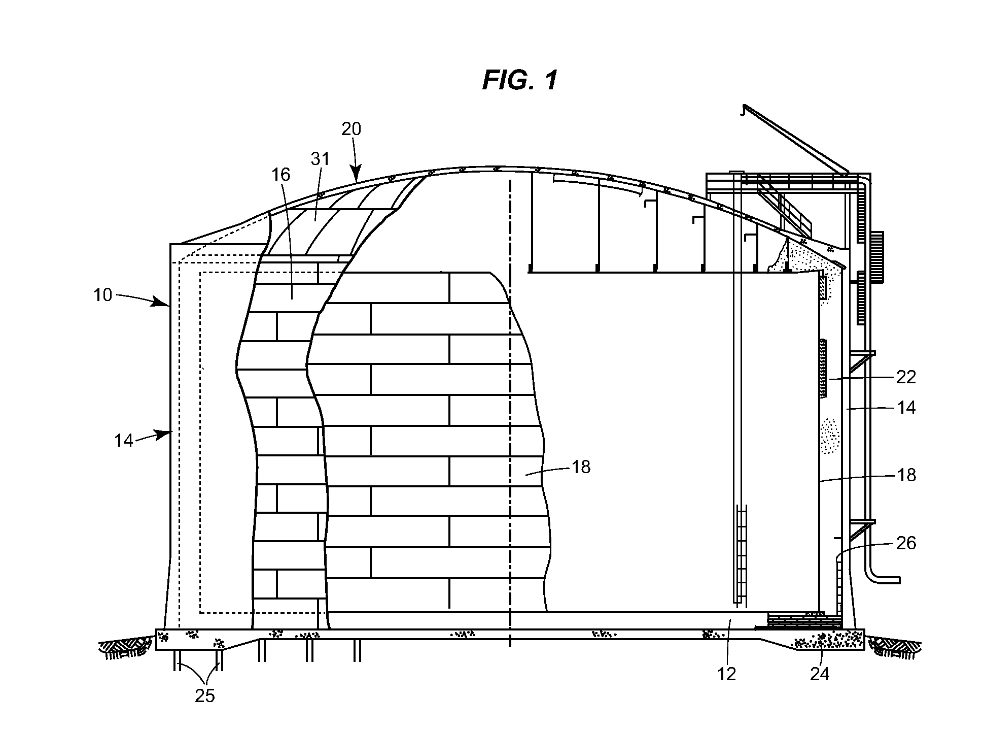
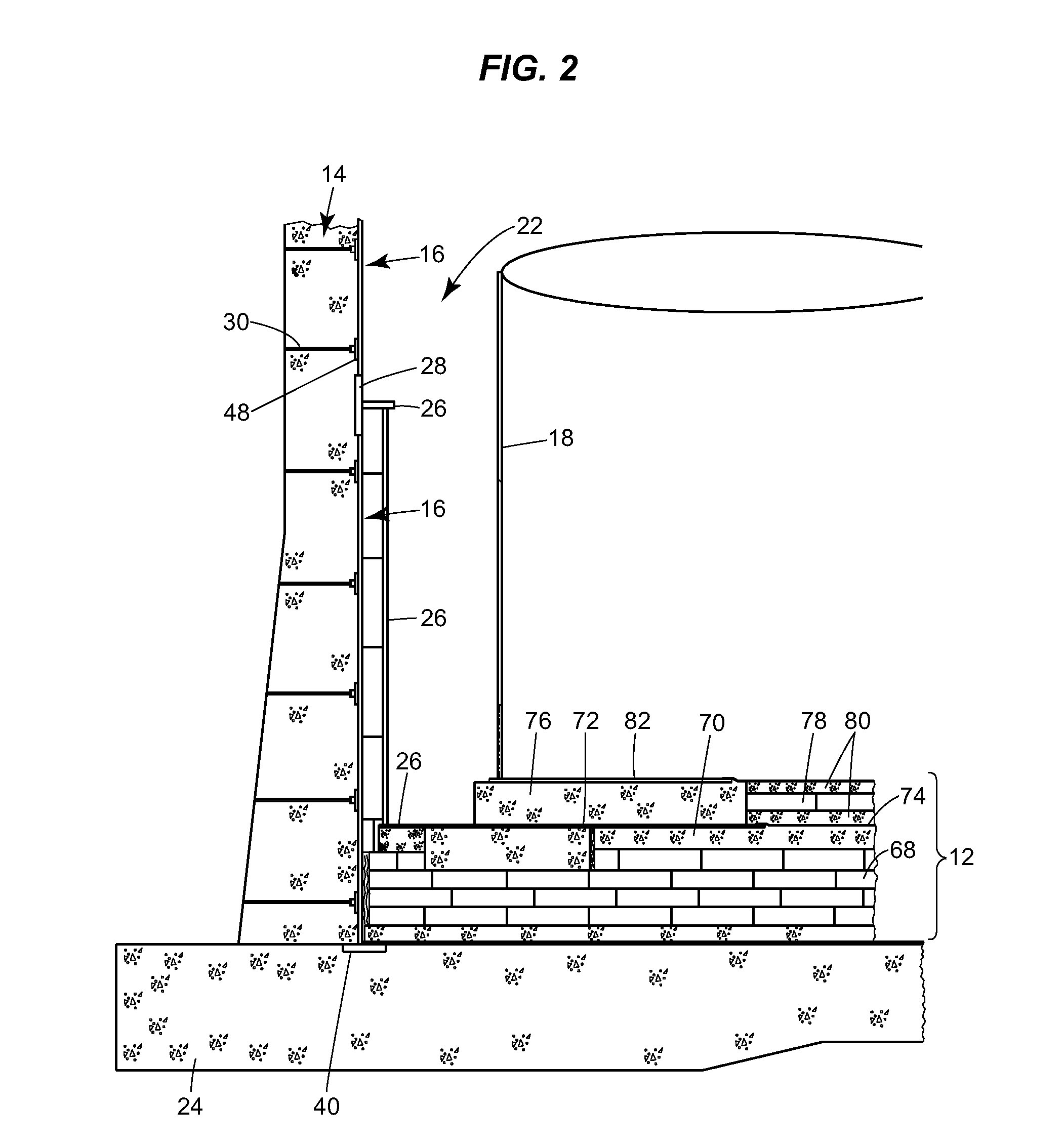
[0022]FIG. 1 illustrates one possible arrangement of a storage tank 10 that incorporates this invention. The illustrated tank is a full-containment storage tank that can be used to store cryogenic liquids like LNG. The illustrated tank 10 has flooring materials 12 (such as cellular glass insulation, a concrete bearing block, metal plates, sand or concrete leveling layers, etc.), an outer concrete wall 14 with a steel liner 16, an inner tank 18, and a roof 20. Insulation 22 is placed between the outer wall and the inner tank. These elements will be discussed briefly below, and the discussion will be followed by one example of how the illustrated tank can be built.

[0023]Elements of the Illustrated Storage Tank

[0024]The flooring materials 12 that are shown in FIG. 1 are supported by a pile cap foundation 24 on piles 25. Alternative arrangements can also be used.

[0025]The outer concrete wall 14 that is illustrated is approximately 36 meters tall, tapers from 0.5 meters to 0.8 meters thi...


PUM

PropertyMeasurementUnit
thicknessaaaaaaaaaa
diameteraaaaaaaaaa
diameteraaaaaaaaaa

Abstract

A new procedure for constructing cryogenic storage tanks involves erecting a freestanding metal liner. The liner is sized and configured to withstand the hydraulic forces the concrete wall of the tank being poured without the need for temporary stiffeners on the inside surface of lower portions of the liner. Lateral tension ties can be connected to anchor ties on an outward surface of the liner and used to tie the liner to outer formwork. These ties may be spaced up to about 2 m apart. Studs can also be provided on the outer surface of the liner, and a cylindrical ring of cryogenic steel can be integrated into the liner.

Description

CROSS-REFERENCE TO RELATED APPLICATIONS[0001]Not applicable.STATEMENT REGARDING FEDERALLY SPONSORED RESEARCH OR DEVELOPMENT[0002]Not applicable.REFERENCE TO A COMPACT DISK APPENDIX[0003]Not applicable.BACKGROUND OF THE INVENTION[0004]The present invention relates generally to storage tanks for cryogenic liquids, and more particularly to “double” and “full” containment storage tanks for cryogenic liquids.[0005]Liquefied natural gas (LNG) is transported and frequently stored at temperatures around −261 F (−163 C). Other gases commonly stored in liquid phase below ambient temperatures include ammonia, propane, butane, LPG, ethylene, oxygen, argon, nitrogen, hydrogen, and helium. LNG storage tanks are generally field-erected vessels in sizes of 315,000 to 1,000,000 barrels (50,000 to 200,000 cubic meters).[0006]It is not uncommon for storage tanks for these liquids to have a form of secondary containment. Free-standing tanks often include an inner tank made of stainless steel, aluminum,...

Claims


Application Information

Patent Timeline
Patent Type & Authority Applications(United States)
IPC IPC(8): F17C1/12
CPCF17C3/022F17C2201/0104F17C2201/032F17C2201/052F17C2203/0629F17C2203/0678F17C2209/232F17C2221/011F17C2221/012F17C2221/014F17C2221/016F17C2221/017F17C2221/033F17C2221/035F17C2223/0161F17C2223/033F17C2260/011F17C2260/013F17C2270/0136Y02E60/321Y02E60/32F17C3/00F17C13/00
Inventor SIMMONS, J. RICKYDYSON, PAUL
Owner CHICAGO BRIDGE & IRON CO
Why Eureka
Try Eureka