Inductor

a technology of inductance and transformer, applied in the field of inductance, can solve the problems of power source efficiency reduction and inductance drop

Inactive Publication Date: 2008-12-11
TOKIN CORP
View PDF15 Cites 57 Cited by
  • Summary
  • Abstract
  • Description
  • Claims
  • Application Information

AI Technical Summary

Benefits of technology

[0009]The present invention solves the above problems, and provides an inductor of small size and low height so as to suit to the miniaturization of a DC-DC converter.

Problems solved by technology

When the coupling coefficient becomes larger than the specified value, a leakage inductance lowers, and a DC-DC converter using a coupling inductor enlarges in a ripple current and lowers in power source efficiency.

Method used


Image

  • Inductor
  • Inductor
  • Inductor

Examples


example 1

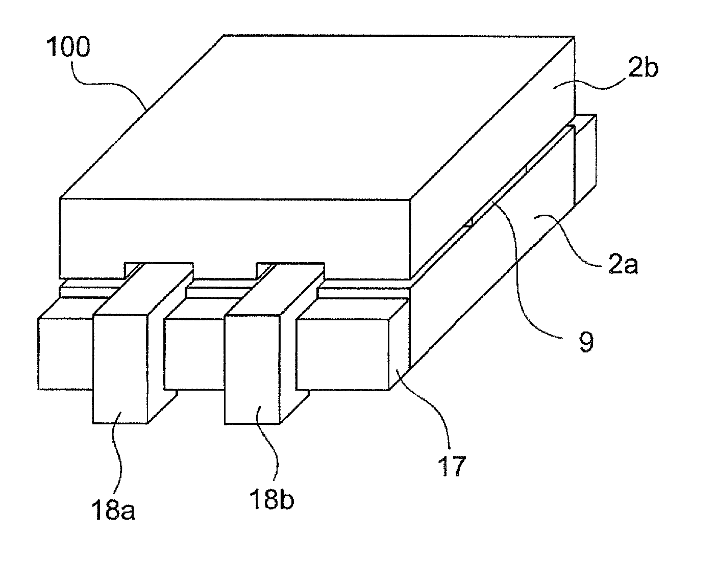
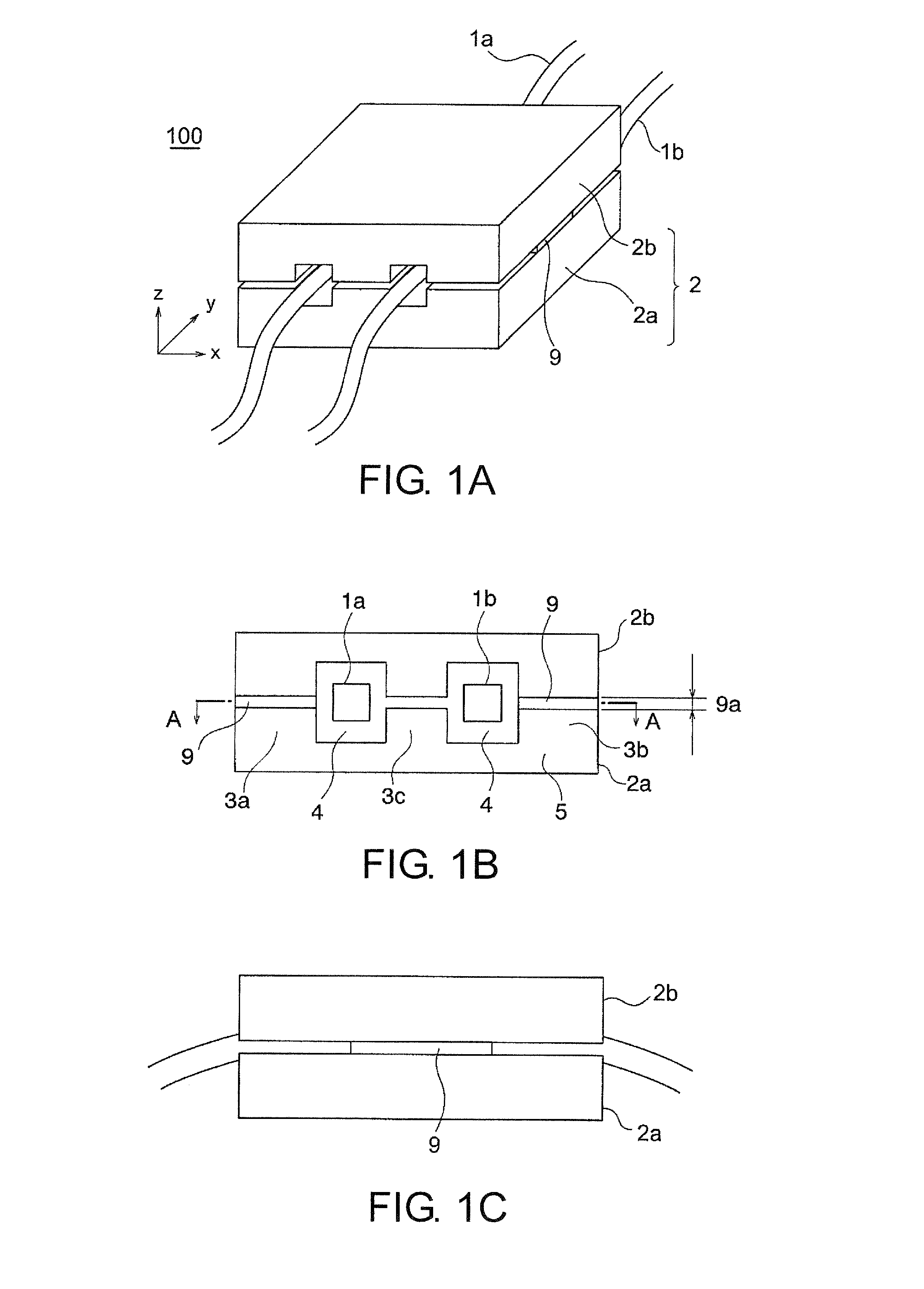
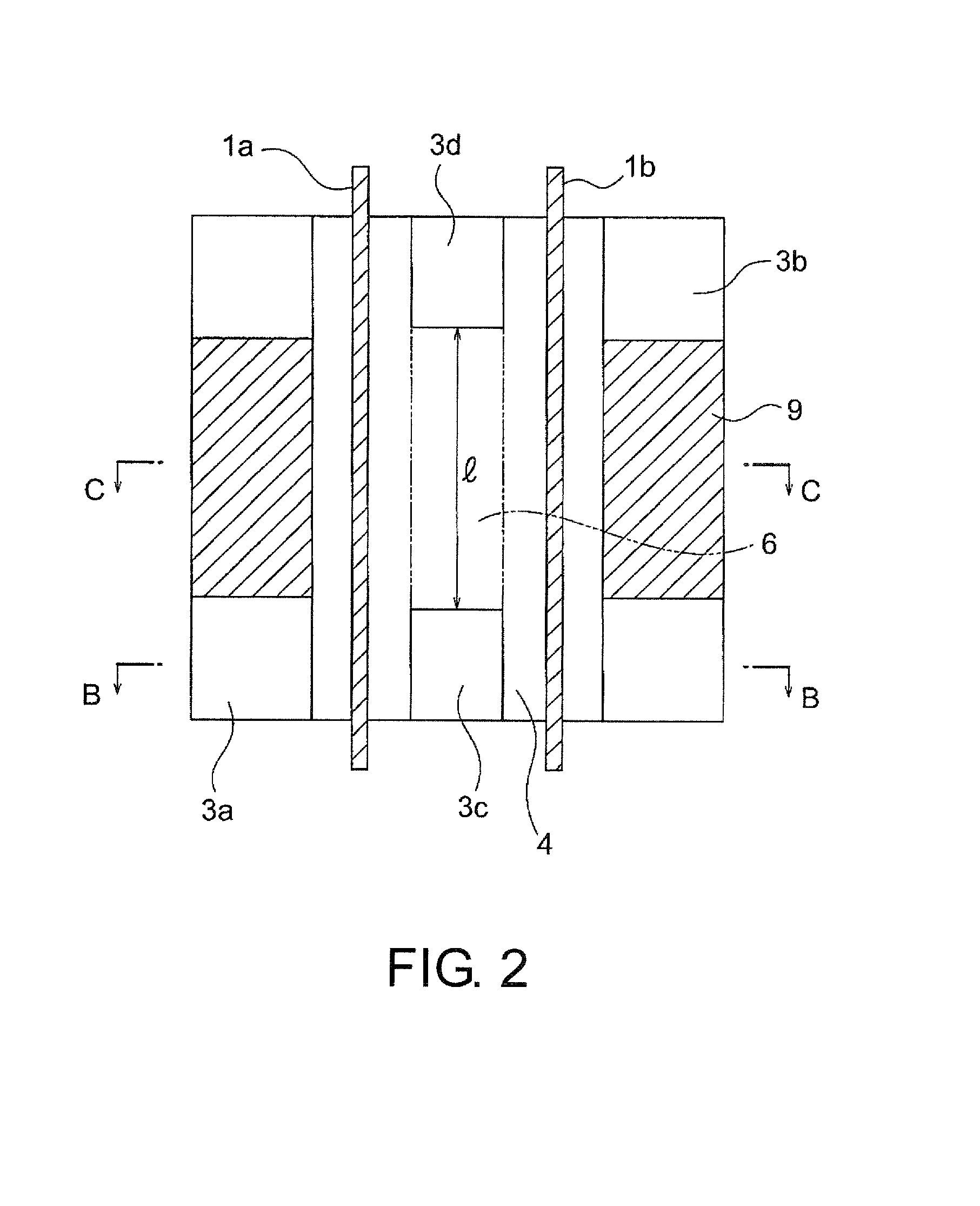
[0082]Using an NiZn ferrite which had a permeability of 600 and a saturation flux density of 450 mT, a second magnetic substance core 2a of E-type as shown in FIG. 2 was prepared so as to have a width of 8 mm, a length of 12 mm and a height of 3.6 mm. A first magnetic substance core 2b to pair with the second magnetic substance core 2a was also prepared in the same shape as that of the second magnetic substance core 2a. The outer legs 3a and 3b and the middle legs 3c and 3d of these cores 2a and 2b were butted against each other through gap materials 9, into a magnetic substance core assembly 2, whereby an inductor 100 shown in FIG. 1 was fabricated. Besides, each of the middle legs 3c and 3d of the magnetic substance cores was configured having a width of 1.0 mm and a length of 1.0 mm. Further, each of the middle-leg non-formation parts of the magnetic substance cores was so configured that its length l was 10 mm, and each of voids 4 serving as the inlets / outlets of conductors was ...

example 2

[0086]In this example, an inductor was fabricated under the same conditions as in Example 1, except that only the length l of the middle-leg non-formation part in Example 1 was altered. Table 2 indicates the list of the electrical performances of the inductor in Example 2.

TABLE 2Middle-legnon-formationCouplingSelf-InductanceLeakage Inductancepart (mm)Coefficient KLs (μH)(μH)00.550.640.2920.600.630.2540.650.610.2280.760.570.14120.920.520.04

[0087]From the result of Table 2, it has been confirmed that the coupling coefficient K and the leakage inductance are respectively adjustable in a range of from 0.55 to 0.92 and in a range of from 0.29 to 0.04 by changing the length of the middle-leg non-formation part.

example 3

[0088]In this example, an inductor was fabricated under the same conditions as in Example 2, except that an MnZn ferrite having a permeability of 2200 and a saturation flux density of 510 mT was employed. Table 3 indicates the list of the electrical performances of the inductor in Example 3.

TABLE 3Middle-legnon-formationCouplingSelf-InductanceLeakage Inductancepart (mm)Coefficient KLs (μH)(μH)00.560.870.3920.610.800.3540.660.830.2980.780.780.10120.940.710.05

[0089]Table 3 indicates the coupling coefficient K and the inductances depending on changes in the length l of the middle-leg non-formation part in the case of employing the MnZn ferrite core assembly. It is seen from the result of Table 3 that the coupling coefficient K exhibits almost the same values as in the case of employing the NiZn ferrite in Table 2, but that the self-inductance Ls has attained larger values in correspondence with the higher permeability of the material Thus, it has been confirmed that, even in the case o...


PUM

PropertyMeasurementUnit
saturation flux densityaaaaaaaaaa
currentaaaaaaaaaa
currentaaaaaaaaaa

Abstract

An inductor includes a first magnetic substance core which has a middle leg, a first outer leg, a second outer leg, and a body portion interconnecting the middle leg, the first outer leg and the second outer leg, and a second magnetic substance core which is arranged to be opposed to the first magnetic substance core. A first conductor is arranged in a first space which is formed by the middle leg, the first outer leg, part of the body portion, and the second magnetic substance core. A second conductor is arranged in a second space which is formed by the middle leg, the second outer leg, part of the body portion, and the second magnetic substance core. The middle leg is formed with a region which is lower in height than the first outer leg, in the same direction as the longitudinal direction of the first outer leg.

Description

[0001]This application is based upon and claims the benefit of priority from Japanese patent application No. 2007-153030, filed on Jun. 8, 2007, and Japanese patent application No. 2008-114382, filed on Apr. 24, 2008, the disclosures of which are incorporated herein in their entirety by reference.TECHNICAL FIELD[0002]The present invention relates to an inductor, and more particularly to an inductor which is well suited for use in a power source that is configured on the board of an electronic device such as DC-DC converter.BACKGROUND ART[0003]A DC-DC converter configured using a plurality of coil components can feed as large a current as 20 A or 30 A, in spite of a small size. Therefore, it has come to be arranged on a board as the power source of a CPU.[0004]In recent years, an LSI or the like has lowered a drive voltage for the purpose of power consumption reduction. With the lowering of the drive voltage, a required current has come to reach several tens of ampere, and a voltage ...

Claims


Application Information

Patent Timeline
Patent Type & Authority Applications(United States)
IPC IPC(8): H01F27/24
CPCH01F3/14H01F17/043H01F27/2847
Inventor YAMADA, SEIICHITAKAHATA, OKIKUNIKAMATA, HIROYUKITSUDA, FUMISHIROUKONDO, MASAHIRO
Owner TOKIN CORP
Why Eureka
Try Eureka