Rail Sensing Apparatus Method

a technology of sensing apparatus and rail, which is applied in the direction of material analysis through optical means, instruments, roads, etc., can solve the problems of excessive wheel and rail wear and/or derailment of vehicles, excessive steering force of bogies, and excessive bogies

Active Publication Date: 2008-12-11
PROGRESS RAIL SERVICES
View PDF1 Cites 73 Cited by
  • Summary
  • Abstract
  • Description
  • Claims
  • Application Information

AI Technical Summary

Benefits of technology

[0008]Certain railway industry derailments of longer vehicles that have been historically categorized to be of undetermined or exceptional cause by the industry are now believed to be related to an unusually high value of the ratio of Lateral over Vertical for...

Problems solved by technology

Railway vehicles with bogies that steer with excess forces, with bogies that are not correctly dynamically damped and thus exhibit excess rail to rail hunting, or with wheel sets with locked brakes and other similar symptoms can result in excess wheel and rail wear and/or derailments of the vehic...

Method used


Image

  • Rail Sensing Apparatus Method
  • Rail Sensing Apparatus Method
  • Rail Sensing Apparatus Method

Examples


Embodiment Construction

[0022]A rail displacement measuring device may be used to obtain data indicative of the loads that a rail vehicle wheel exerts on the rail as the vehicle rolls past the measuring device. The data is then processed to extract information indicative of the health of the rolling mechanisms associated with the vehicle.

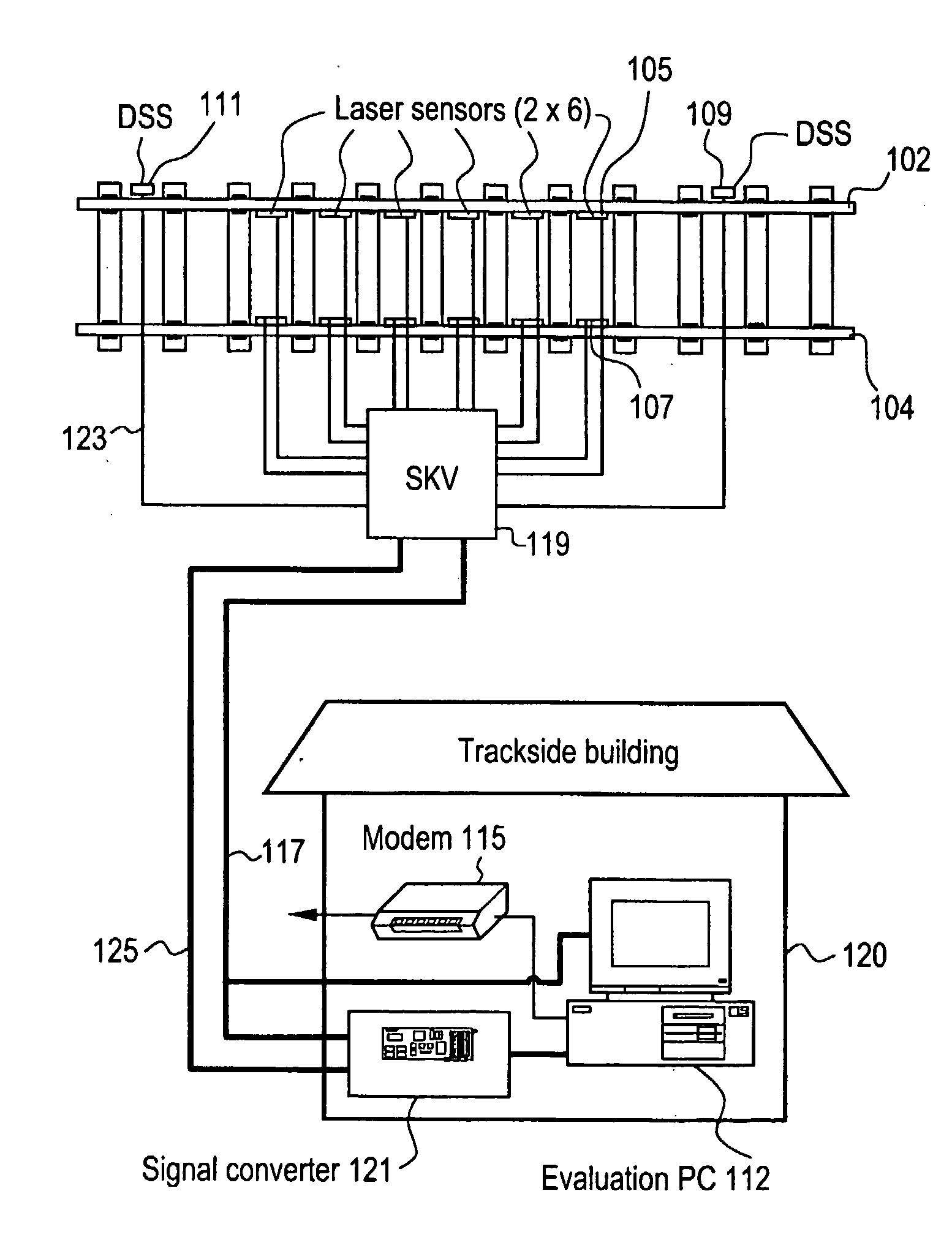
[0023]FIG. 1 illustrates an exemplary rail sensing and analysis system. One or more sensors are placed in position along a track to obtain information from the rail(s) as a rail vehicle passes. In the embodiment of FIG. 1, six laser sensors 105, 107 are positioned along each of two parallel track rails, 102, 104. The laser sensors 105, 107 provide a signal responsive to deflection of the rails 102, 104, such as by the lateral and vertical forces exerted on the rails by the wheels of a passing rail vehicle. Laser detectors and deflection monitoring devices are described in published European patent documents WO 01 / 18487 A1 and WO 2004 / 005864 A1, incorporated by reference he...


PUM


Abstract

A rail sensing and analysis system utilizes a laser sensor 105, 107 to detect displacement of a rail 102, 104 resulting from loads imposed by a passing rail vehicle. Vertical and/or lateral displacements/loads may be sensed. Signatures in the resulting signals are indicative of useful information about the rail vehicle; such as wheel condition, bearing condition, truck condition, degree of bogie hunting, total load, load distribution, etc. The ratio of Lateral over Vertical force (L/V) may be used as an evaluation criterion.

Description

CROSS-REFERENCE TO A RELATED APPLICATION[0001]This application claims the benefit of U.S. Provisional Patent Application Ser. No. 60 / 609,053 filed Sep. 11, 2004, incorporated herein by reference.BACKGROUND[0002]The safe and reliable operation of a railroad system is dependent upon the integrity of the rolling mechanisms of the vehicles traveling over the rails. The wheel sets and bogies of train vehicles are routinely inspected to ensure that they are in proper operating order. Periodic inspections during maintenance intervals are effective for identifying failed and degrading components. However, the frequency of such inspections is not always adequate due to the nature of certain modes of degradation. For example, a wheel may develop a flat spot during operation due to the application of vehicle brakes causing the wheel to skid along the track. Once a flat spot, or some other defect, is created, there may be excessive vibration and other impacts and defects that leads to mechanica...

Claims


Application Information

Patent Timeline
IPC IPC(8): G01B11/00
CPCE01B35/00G01M17/10
Inventor HESSER, PETERNOFFSINGER, JOSEPH FORRESTSHANAHAN, THOMAS MICHAEL
Owner PROGRESS RAIL SERVICES
Why Eureka
Try Eureka