Internet Latencies Through Prediction Trees

a prediction tree and network latencies technology, applied in data switching networks, instruments, frequency-division multiplexes, etc., can solve the problems of computationally expensive and time-consuming network communication, determine such network performance characteristics, and achieve accurate representation of latency between nodes, no additional network overhead, and no additional overhead.

Inactive Publication Date: 2008-12-11
MICROSOFT TECH LICENSING LLC
View PDF14 Cites 46 Cited by
  • Summary
  • Abstract
  • Description
  • Claims
  • Application Information

AI Technical Summary

Benefits of technology

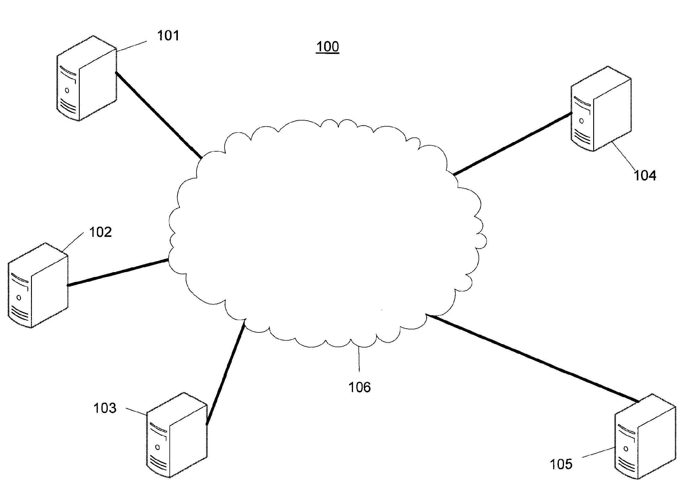
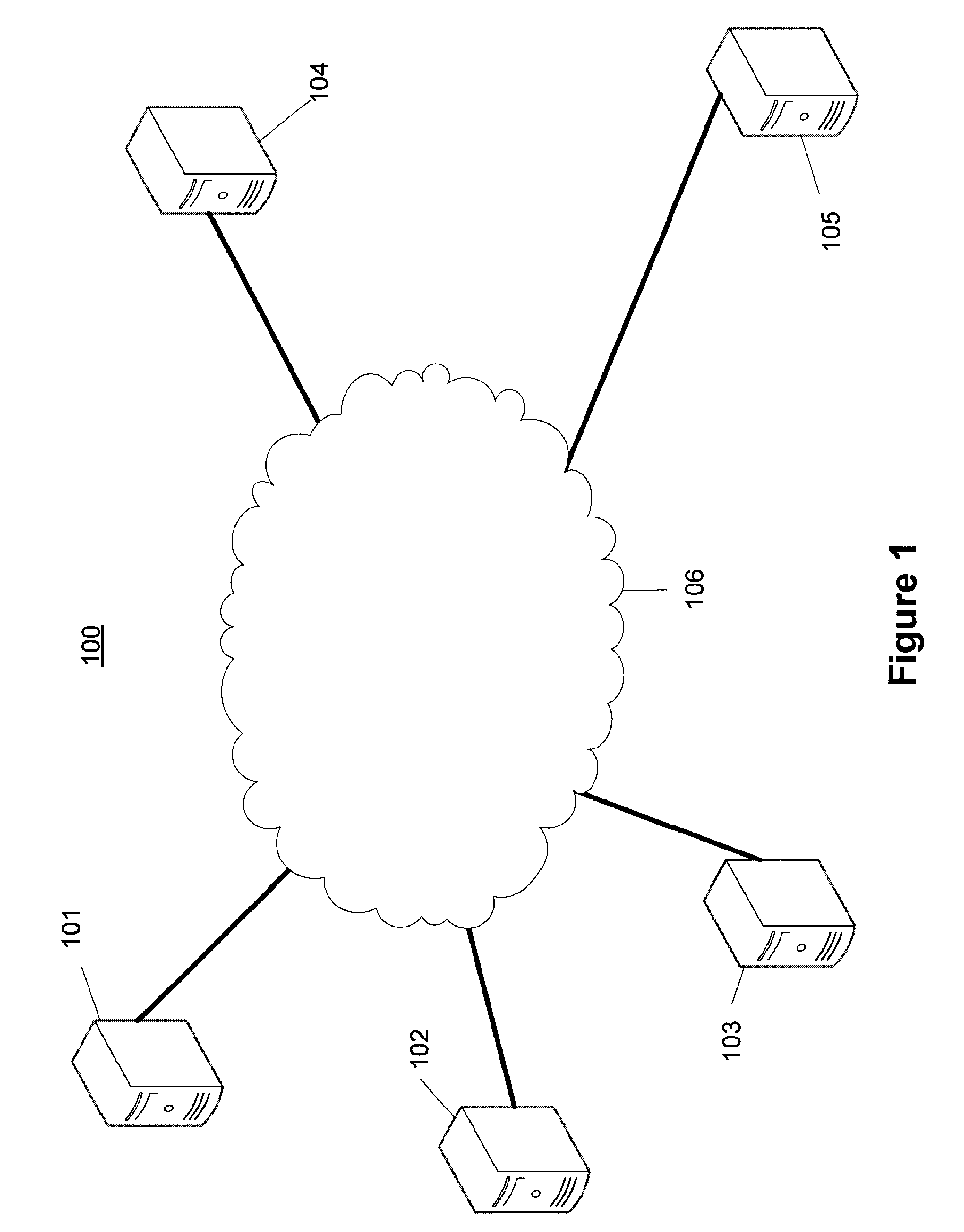
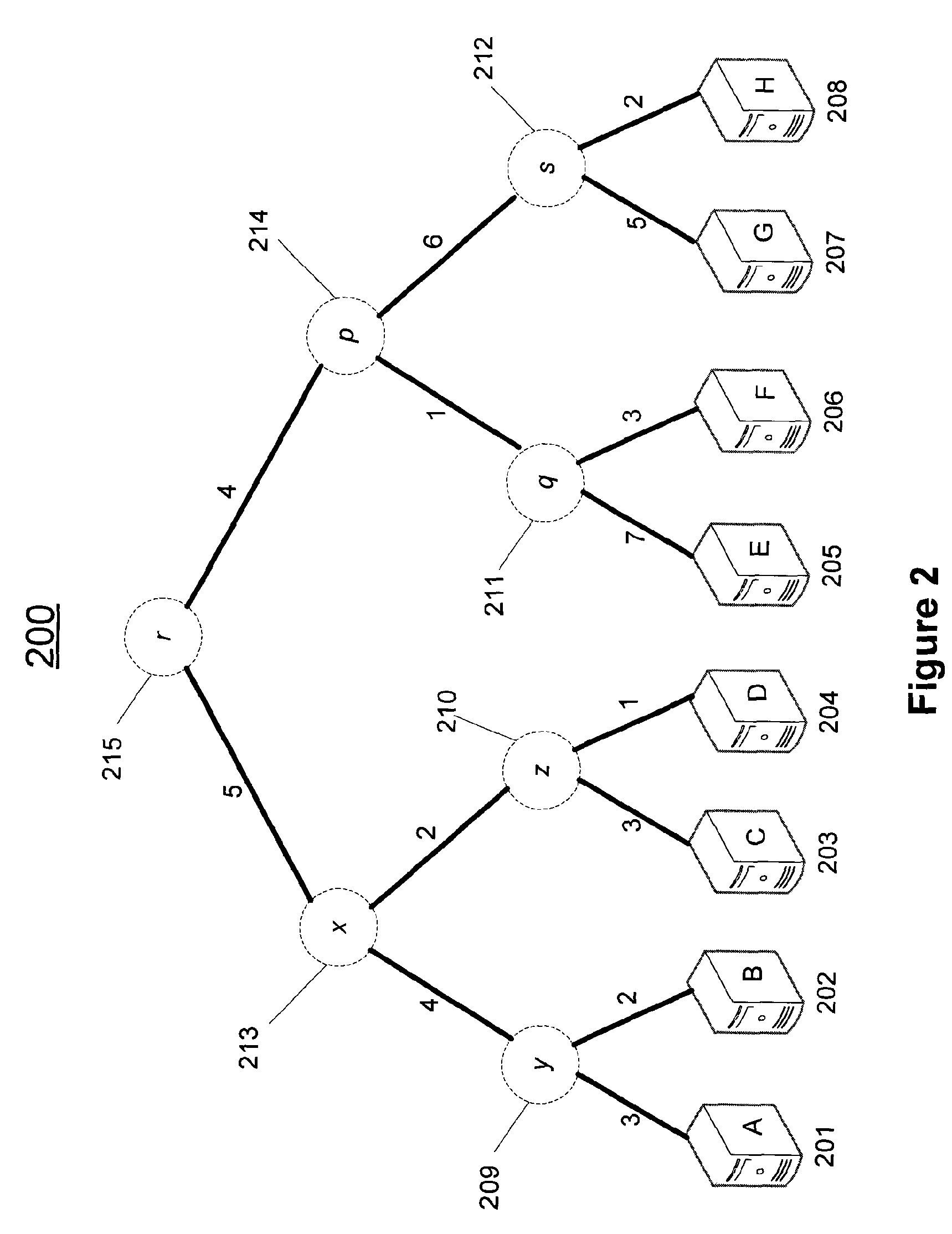
[0009]Methods and systems for modeling inter-nodal network performance parameters, such as latency, are described herein. A prediction tree is a virtual topology of a network, where virtual nodes connect real end hosts, and carefully computed edge weights model a network parameter, such as latency. Prediction trees may support several application-level functionalities such as closest-node discovery and locality-aware clustering without placing undue additional burdens on the network. Some applications, such as for example, content distribution networks, can benefit from the ability to estimate network latency between end hosts instantaneously, without incurring the overhead of recurrent measurements.
[0010]Mechanisms are described for constructing a virtual topology of the network that accurately represents latency between nodes. The described approach for modeling the internal structure of the network enables intrinsic support of functionalities such as latency prediction, closest node discovery, and proximity-based clustering with little additional network overhead. The virtual topology used to model the network is a tree. Although many networks are decidedly non-treelike, the prediction trees described herein provide robust models for estimating important network metrics. Mechanisms described herein maintain a collection of virtual trees between participating nodes and handle changes in network latencies, tolerate network and node failures, and scale well as new nodes join the system.

Problems solved by technology

Generally, determining such network performance characteristics has required computationally expensive and time consuming network communications.

Method used


Image

  • Internet Latencies Through Prediction Trees
  • Internet Latencies Through Prediction Trees
  • Internet Latencies Through Prediction Trees

Examples


Embodiment Construction

[0025]Certain specific details are set forth in the following description and figures to provide a thorough understanding of various embodiments of the invention. Certain well-known details often associated with computing and software technology are not set forth in the following disclosure to avoid unnecessarily obscuring the various embodiments. Further, those of ordinary skill in the relevant art will understand that they can practice other embodiments without one or more of the details described below. Finally, while various methods are described with reference to steps and sequences in the following disclosure, the description as such is for providing a clear implementation of embodiments of the invention, and the steps and sequences of steps should not be taken as required to practice this invention.

[0026]It should be understood that the various techniques described herein may be implemented in logic realized with hardware or software or, where appropriate, with a combination ...


PUM


Abstract

A prediction tree for estimating values of a network performance measure. Leaf nodes of the prediction tree are associated with networked computing devices and interior nodes are not necessarily representative of physical network connections. Values are assigned to edges in the prediction tree and the network performance measure relative to two computing devices represented by two nodes of the tree is estimated by aggregating the values assigned to the edges in the path in the prediction tree joining the two edges. Mechanisms for adding nodes representing computing devices to the prediction tree, for identifying a closest node representing a computing device in the prediction tree, for identifying a cluster of devices represented by nodes of the tree, and for rebalancing the prediction tree are provided.

Description

BACKGROUND OF THE INVENTION[0001]A computer network may comprise multiple computing devices interconnected by a communications system. Networking generally enables computers to do much more than communicate. Networked computers can share resources, including such things as: peripheral devices such as printers, disk drives, and routers; software applications; and data. Rapid growth in the use of computers and computer networks and the progression from mainframe computing to client-server applications and distributed computing have fueled interest in network performance optimization, network-aware applications and network modeling in general.[0002]Network topology refers to the arrangement of the elements in a network, and especially the physical and logical interconnections between nodes of the network. Common basic network topologies include: a linear bus, in which nodes of the network are connected to a common communications backbone; a star, in which nodes are directly connected t...

Claims


Application Information

Patent Timeline
Patent Type & Authority Applications(United States)
IPC IPC(8): H04L12/26
CPCH04L41/147H04L43/0852
Inventor RAMASUBRAMANIAN, VENUGOPALAN SARASWATIMALKHI, DAHLIABALAKRISHNAN, MAHESHKUHN, FABIAN DANIELABRAHAM, ITTAI
Owner MICROSOFT TECH LICENSING LLC
Why Eureka
Try Eureka