Method and system for performing high temporal resolution bolus detection using CT image projection data

a computed tomography and image projection technology, applied in image enhancement, instruments, angiography, etc., can solve the problems of patient exposure to unnecessary radiation for a period of time, poor visualization of blood vessels of interest, and difficulty in determining the arrival of contrast medium in the area of interes

Active Publication Date: 2008-12-11
GENERAL ELECTRIC CO
View PDF6 Cites 21 Cited by
  • Summary
  • Abstract
  • Description
  • Claims
  • Application Information

AI Technical Summary

Problems solved by technology

Conventional CT medical imaging systems that acquire images without using a contrast agent result in poor visualization of the blood vessels of interest.
Using current medical imaging systems, it is often difficult to determine when the contrast medium arrives at an area of interest.
By starting the imag

Method used


Image

  • Method and system for performing high temporal resolution bolus detection using CT image projection data
  • Method and system for performing high temporal resolution bolus detection using CT image projection data
  • Method and system for performing high temporal resolution bolus detection using CT image projection data

Examples


Embodiment Construction

[0015]In the following detailed description, reference is made to the accompanying drawings which form a part hereof, and in which is shown by way of illustration specific embodiments in which the present invention may be practiced. These embodiments, which are also referred to herein as “examples,” are described in sufficient detail to enable those skilled in the art to practice the invention, and it is to be understood that the embodiments may be combined, or that other embodiments may be utilized and that structural, logical and electrical changes may be made without departing from the scope of the various embodiments of the present invention. The following detailed description is, therefore, not to be taken in a limiting sense, and the scope of the present invention is defined by the appended claims and their equivalents.

[0016]In this document, the terms “a” or “an” are used, to include one or more than one. In this document, the term “or” is used to refer to a nonexclusive or, ...


PUM


Abstract

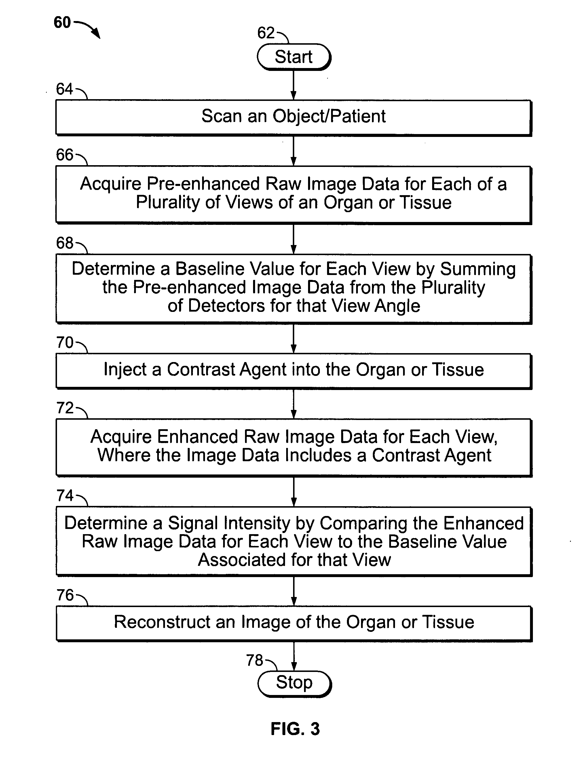
A method of evaluating changes in contrast of an image using a diagnostic imaging system is provided. The method provides acquiring raw image data of an organ or tissue, calculating a baseline of data based on the raw image data acquired before arrival of an agent, and determining changes in a signal intensity of the agent based on changes in the raw image data compared to the baseline. The agent may be an imaging agent, a contrast agent, a biomedical agent, a needle, a catheter, a biomedical device, and the like.

Description

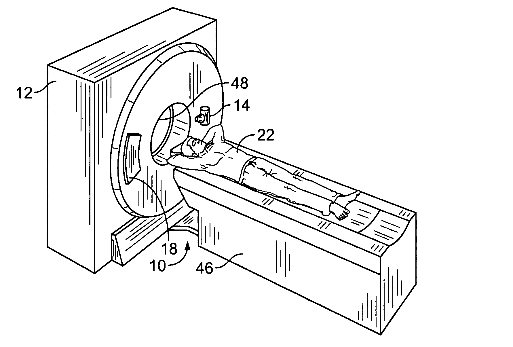
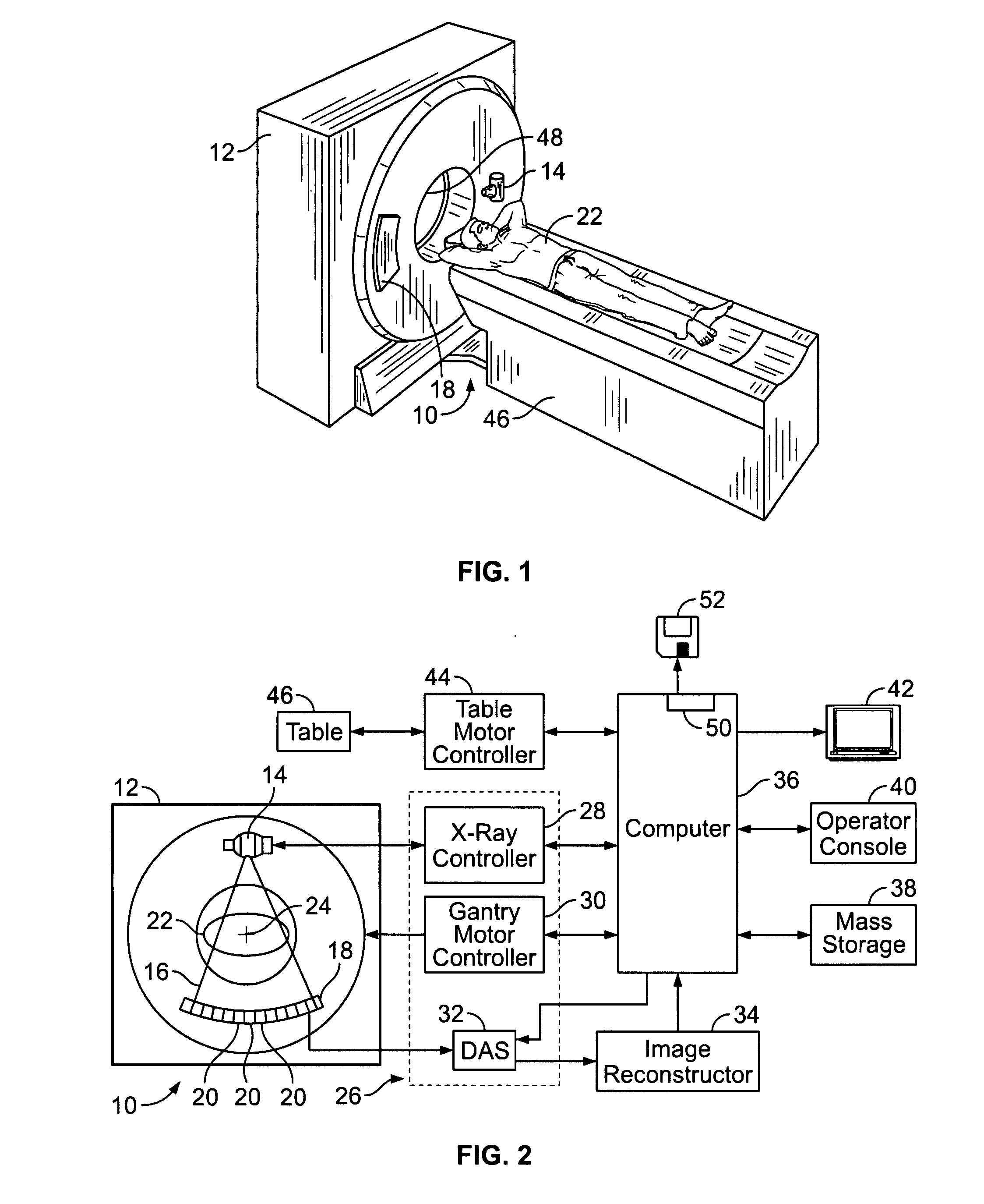
BACKGROUND OF THE INVENTION[0001]The invention relates generally to methods and apparatus for computed tomography (CT) imaging, and more particularly to methods and apparatus for updating rendered images using CT image projection data.[0002]In certain known CT imaging systems, an x-ray source transmits x-ray beams towards an object of interest. The x-ray beams pass through the object being imaged, such as a patient. The beams, after being attenuated by the object, impinge upon an array of radiation detectors. The intensity of the attenuated beam radiation received at the detector array is dependent upon the attenuation of the x-ray beam by the object. Each detector element of the array produces a separate electrical signal that is a measurement of the beam attenuation at the detector location. Attenuation measurements from the detectors are acquired separately for each detector element and collectively define a projection data set or transmission profile.[0003]The x-ray source and t...

Claims


Application Information

Patent Timeline
IPC IPC(8): G06K9/00
CPCA61B6/03A61B6/481A61B6/507G06T7/20G06T2207/10081A61B6/504
Inventor LICATO, PAUL E.HOPPEL, BERNICE E.
Owner GENERAL ELECTRIC CO
Why Eureka
Try Eureka