Systems and methods for detection of an airborne contaminant

a technology of airborne contaminant and detection system, which is applied in the direction of instruments, material analysis, and withdrawal sample devices, etc., can solve the problems of increasing the toxicity of the attack, releasing toxic industrial gases and irritants, and insufficient airborne contamination detections to address the increased risk posed by current world events

Inactive Publication Date: 2008-12-11
DRS SUSTAINMENT SYST
View PDF2 Cites 16 Cited by
  • Summary
  • Abstract
  • Description
  • Claims
  • Application Information

AI Technical Summary

Benefits of technology

[0015]In accordance with systems consistent with the present invention, a system for detection of an airborne contaminant in a detection system is provided. The system comprises a air sample capture system configured to receive an air sample from the atmospheric environment; a contaminant sample separation system effective to receive the air sample from the air sample capture system and to separate particles of interest from particles of non interest in the air sample to form a candidate sample; a contaminant sample imaging device effective to receive a candidate sample from the contaminant sample separation system and generate an image of the candidate sample; and a contaminant sample imaging analyzing system effective to receive a contaminant image sample from the contaminant sample imaging system and detect the presence of a contaminant in the candidate sample by comparing the candidate sample images with a plurality of stored reference images, each of which reflects a respective identified contaminant.

Problems solved by technology

The detection of airborne contaminants has received increased attention recently and has resulted in the realization that current airborne contamination detections are inadequate to address the increased risk posed by current world events.
Household materials mixed in specific manner may release toxic industrial gases and irritants which may be used to affect large groups of people.
The inclusion of biological material as an airborne contaminant may increase the toxicity of the attack and presents a particularly troublesome issue due to the wide variety and accessibility of biological materials in laboratories, hospitals and university settings.
Current airborne contamination detection systems do not provide timely detection to ensure that adequate warning and corrective measures are implemented.
However, the real-time capture and identification of airborne contaminants poses significant challenges including sample capture and preparation without exposure, quick and accurate identification of the agent, immediate warning and implementation of corrective and remediation efforts, and subsequent sterilization of the apparatus used for monitoring and analysis.
Typically, the real-time capture and identification of airborne contaminants is not comprehensive and is limited to very few contaminants using rudimentary spot checks performed in-situ.
Many times the concentration of the airborne contaminant is not sufficient to be detected and thus additional processing is required to culture the contaminant before it may be detected is required.
Such comprehensive remote laboratory testing is inadequate to deal with the current threat of airborne contamination due to the inability of the current systems to quickly analyze and detect airborne contamination in-situ.
For example, remote laboratory analysis is not realistic for monitoring the local atmospheric environment of shipping containers, ventilation ducts, airplane cabins or other confined spaces.
Current in-situ detectors do not perform the comprehensive testing required to identify the myriad of ever changing airborne contaminant threats.
Such systems are not adaptable to detect the current expected threat and provide only rudimentary detection similar to that provided by a common smoke detector.
Another problem which plaques such prior art sampling and detection systems is that many samples are required to be drawn due to the number of different tests which must be performed on the samples, as well as the need to ensure the sample adequately represents the atmospheric environment being tested.
The requirement for drawing many samples ultimately results in the generation of contaminated sampling equipment which must then be adequately controlled and subsequently sterilized.
Additionally, existing screening systems are generally limited to examination of large boxes and packages, and only screen for items that may be detected by x-ray or similar non-invasive scanners.
These systems, while often effective for detecting bombs, are generally unable to detect dangerous powders, liquids, or similar materials.
Such decontamination, however, generally does not protect against chemical agents, and further can damage the mail, including its contents.
Moreover, such decontamination is often performed after mail is sorted, and therefore after many persons may have been exposed.
One of the leading problems with aerosolized samples produced by these and other methods for collecting aerosolized samples from mail flats is the large number of particles contained in such samples that are not of interest because they are not the particle of interest nor the residue of interest.
The large number of particles not of interest makes detection of the particles of interest more challenging.

Method used


Image

  • Systems and methods for detection of an airborne contaminant
  • Systems and methods for detection of an airborne contaminant
  • Systems and methods for detection of an airborne contaminant

Examples


Embodiment Construction

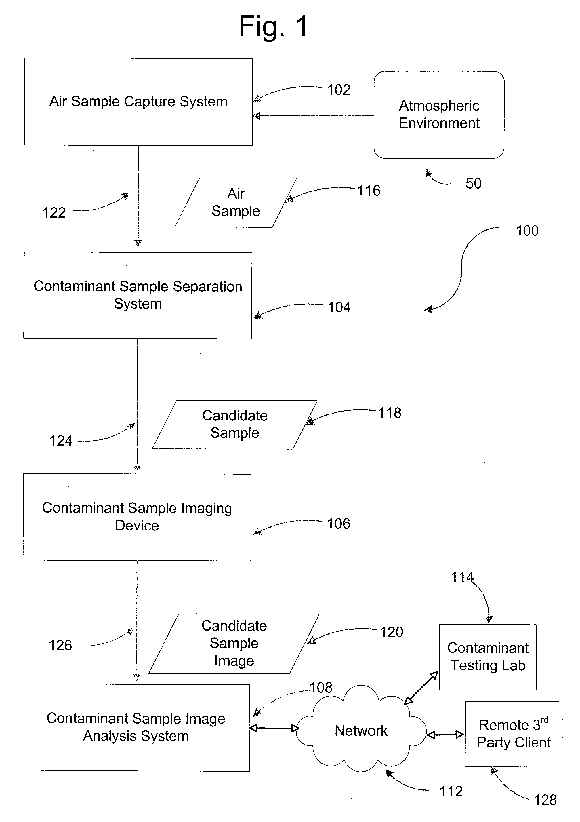
[0030]Referring now to the drawings, FIG. 1 depicts an airborne contaminant detection system 100 consistent with the present invention. The airborne contaminant detection system 100 includes an air sample capture system 102, a contaminant sample separation system 104, a contaminant sample image device 106, and a contaminant sample imaging analysis system 108, which may be operatively connected to a contaminant testing lab 114 and a remote third party 128 via a network 112. The network 112 may be any known private or public communication network such as a Local Area Network (“LAN”), Wide Area Network (“WAN”), Peer-to-Peer Network, or the Internet, using standard communication protocols. The network may include hardwired as well as wireless branches.

[0031]As demonstrated in FIG. 1 and discussed in further detail herein, the air sample capture system 102 is operatively configured to capture an air sample 116 from an atmospheric environment 50 surrounding or in proximity to the air samp...


PUM

PropertyMeasurementUnit
volumeaaaaaaaaaa
diameteraaaaaaaaaa
temperatureaaaaaaaaaa

Abstract

A method is provided for detection of an airborne contaminant in a atmospheric environment. The method comprises capturing an air sample from the atmospheric environment; separating candidate particles of interest from particles of non interest in the air sample; generating an image of the candidate particles; identifying a contaminant from among the candidate particles by comparing the image of candidate particles with a plurality of stored reference images, each of which reflects a respective identified contaminant; and notifying a remote third party in response to detecting a contaminant from among the candidate particles.

Description

CROSS REFERENCE TO RELATED APPLICATIONS[0001]This application claims the benefit of the filing date of U.S. Provisional Applications No. 60 / 893,579, titled “Systems and Method for the Concentration and Detection of Air Samples,” filed on Mar. 7, 2007; U.S. Provisional Application No. 60 / 893,583, filed Mar. 7, 2007 titled “Systems and Methods for the concentration and Detection of Air Sample Residues”; and U.S. Provisional Applications No. 60 / 893,584, filed Mar. 7, 2007, titled “Method and Apparatus for Image Detection of Airborne Contaminants”, all of which are incorporated herein by reference.FIELD OF INVENTION[0002]The present invention relates generally to airborne contaminant detection system, and more particularly to systems and methods for capturing an air sample, separating out candidate contaminants from the sample, detecting a contaminant from among the candidate contaminants and alerting a local authority if a contaminant is detected.[0003]The detection of airborne contami...

Claims


Application Information

Patent Timeline
Patent Type & Authority Applications(United States)
IPC IPC(8): G06K9/64G01N1/28
CPCG01N1/2214G01N1/2273G01N15/1475G01N35/0098G01N2001/2223G01N2015/0088G01N2035/00574
Inventor MATTEONI, JOSEPHBERTRAM, JEFFERY P.MOORE, WAYNE K.NICKELL, DANIEL B.
Owner DRS SUSTAINMENT SYST
Why Eureka
Try Eureka