Motor direct drive air pump and related applications thereof

Inactive Publication Date: 2008-12-11
JAGUAR PRECISION IND
View PDF10 Cites 8 Cited by
  • Summary
  • Abstract
  • Description
  • Claims
  • Application Information

AI Technical Summary

Benefits of technology

[0017]A further objective of the invention is to propose a motor direct drive

Problems solved by technology

This renders the overall size of the ventilation device needlessly large, and results in the fact that the ventilation device must be built with a

Method used


Image

  • Motor direct drive air pump and related applications thereof
  • Motor direct drive air pump and related applications thereof
  • Motor direct drive air pump and related applications thereof

Examples


first embodiment

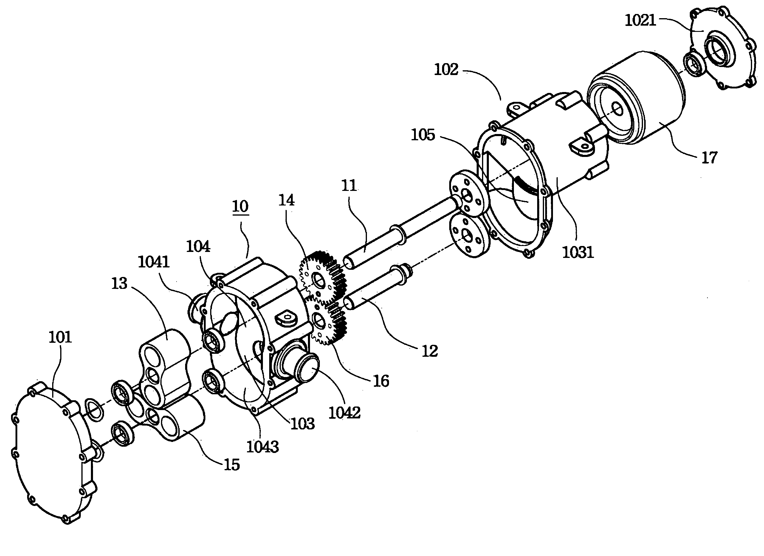
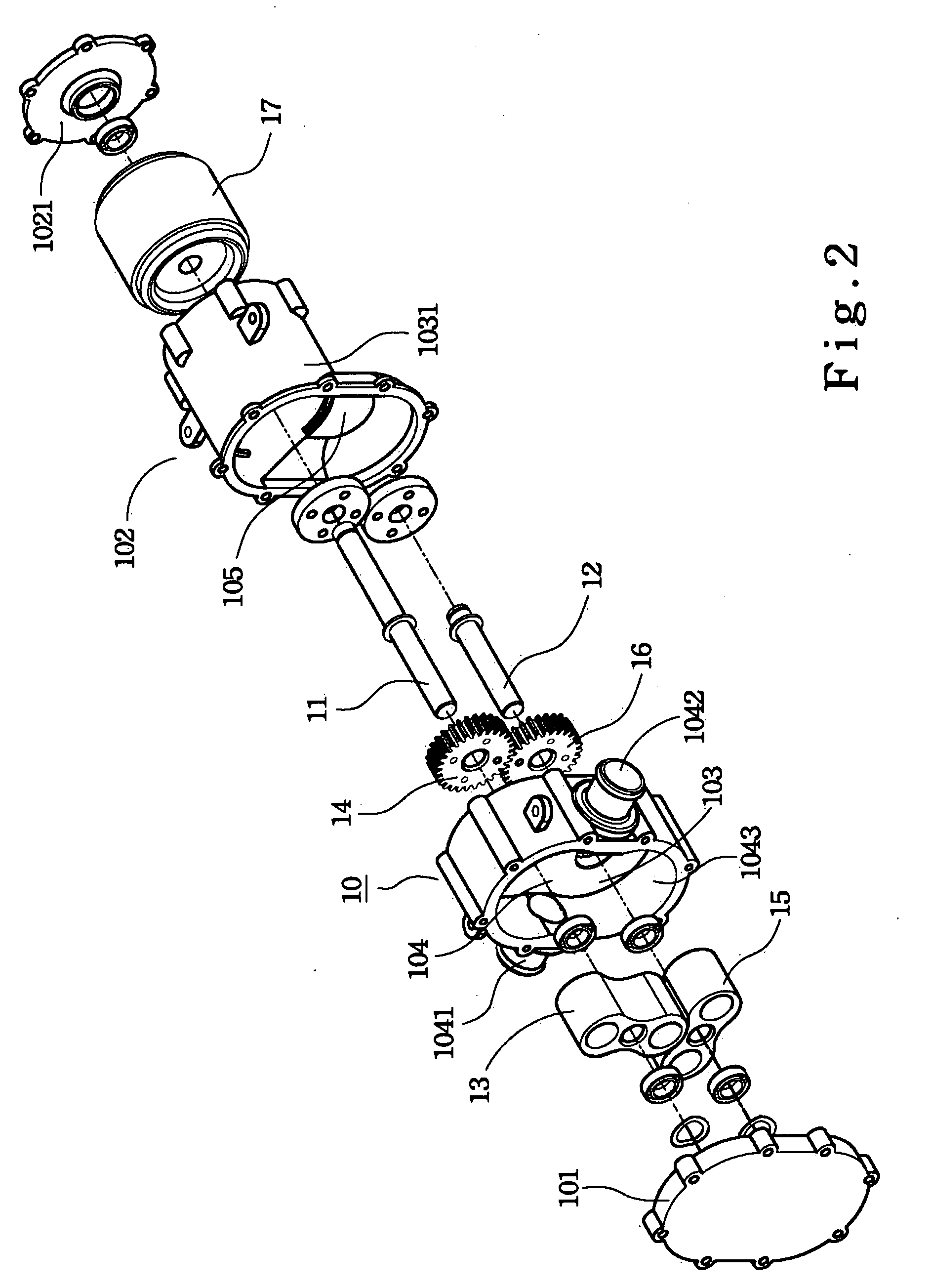
[0039]A third preferred embodiment is shown in FIG. 6, which is a sectional view of a motor direct drive compressor having identical characteristics as the aforesaid However, a compressor requires higher air impermeability than that of an air pump in order to provide compressed air of higher pressure. Therefore, seals 20 such as O-shaped rings are disposed at where the first shaft 11 and the second shaft 12 are fittingly disposed through the central partition 103 in this embodiment, and thinly-formed airtight rings 1011 may also be disposed at where the left cover 101 and the central partition 103 are joined if required. As a result, a power outputted from a motor may directly drive the first impeller and the second impeller in the compression chamber without going through an additional coupling, and allow the compressor to output compressed air from the air outlet.

The Fourth Preferred Embodiment

third embodiment

[0040]A fourth preferred embodiment is shown in FIG. 7, which is a sectional view of a motor direct drive compressor having identical characteristics as the aforesaid However, a compressor requires higher air impermeability than that of an air pump in order to provide compressed air of higher pressure. Therefore, seals 20 such as O-shaped rings are disposed at where the first shaft 11 and the second shaft 12 are fittingly disposed through the central partition 103 in this embodiment, and thinly-formed airtight rings 1021 may also be disposed at where the right cover 102 and the central partition 103 are joined if required. As a result, a power outputted from a motor may directly drive the first impeller and the second impeller in the compression chamber without going through an additional coupling, and allow the compressor to output compressed air from the air outlet.

The Fifth Preferred Embodiment

[0041]The invention further proposes a fifth preferred embodiment, which is a motor di...


PUM


Abstract

A motor direct drive air pump comprises a housing, a first shaft, and a second shaft. The housing is formed with a left space and a right space; one of the spaces is a compression chamber having an air inlet and an air outlet; the other space has a transmission chamber and a driving chamber; stators are disposed in the driving chamber. A first shaft is disposed through a central partition of the housing; a first impeller is embedded at a portion of the first shaft located in the compression chamber, while a first gear is embedded at a portion of the first shaft located in the transmission chamber, and rotors are embedded at a portion of the first shaft located in the compression chamber. A second shaft is disposed through the central partition of the housing; a second impeller is embedded at a portion of the second shaft located in the compression chamber, while a second gear is embedded at a portion of the second shaft located in the transmission chamber, and the second impeller and the second gear are respectively coupled to the first impeller and the first gear. Therefore, a power outputted from a motor directly drives the first and the second impellers and allow the air pump to operate, without any additional coupling.

Description

FIELD OF THE INVENTION[0001]The invention relates to an air pump, and more particularly to a motor direct drive air pump having a motor directly outputs power to drive the air pump, and the outputted power does not need to go through an additional coupling.DESCRIPTION OF PRIOR ART[0002]A conventional ventilation device usually comprises a housing with an air inlet and an air outlet, and has therein a pair of impellers that may be coupled to each other and rotate toward opposite directions, respectively. When one of the impellers passes by the air inlet, a fixed amount of air is captured between the impellers and the housing, then transported and allowed to exit via the air outlet by the rotating impellers. As the rotation of the impellers is repeated, the ventilation device may put out a fixed proportion of air.[0003]A spiral pump of prior arts having a driving valve and a piston was disclosed in the U.S. Pat. No. 4,772,187. A plurality of arc-shaped surfaces are externally disposed...

Claims


Application Information

Patent Timeline
IPC IPC(8): F01C1/10F04C18/08
CPCF04C18/126F04C29/0042
Inventor CHUANG, FEI-TYH
Owner JAGUAR PRECISION IND
Why Eureka
Try Eureka