Gas Quench and Scrubber Draw-Off System
- Summary
- Abstract
- Description
- Claims
- Application Information
AI Technical Summary
Benefits of technology
Problems solved by technology
Method used
Image

Examples
Embodiment Construction
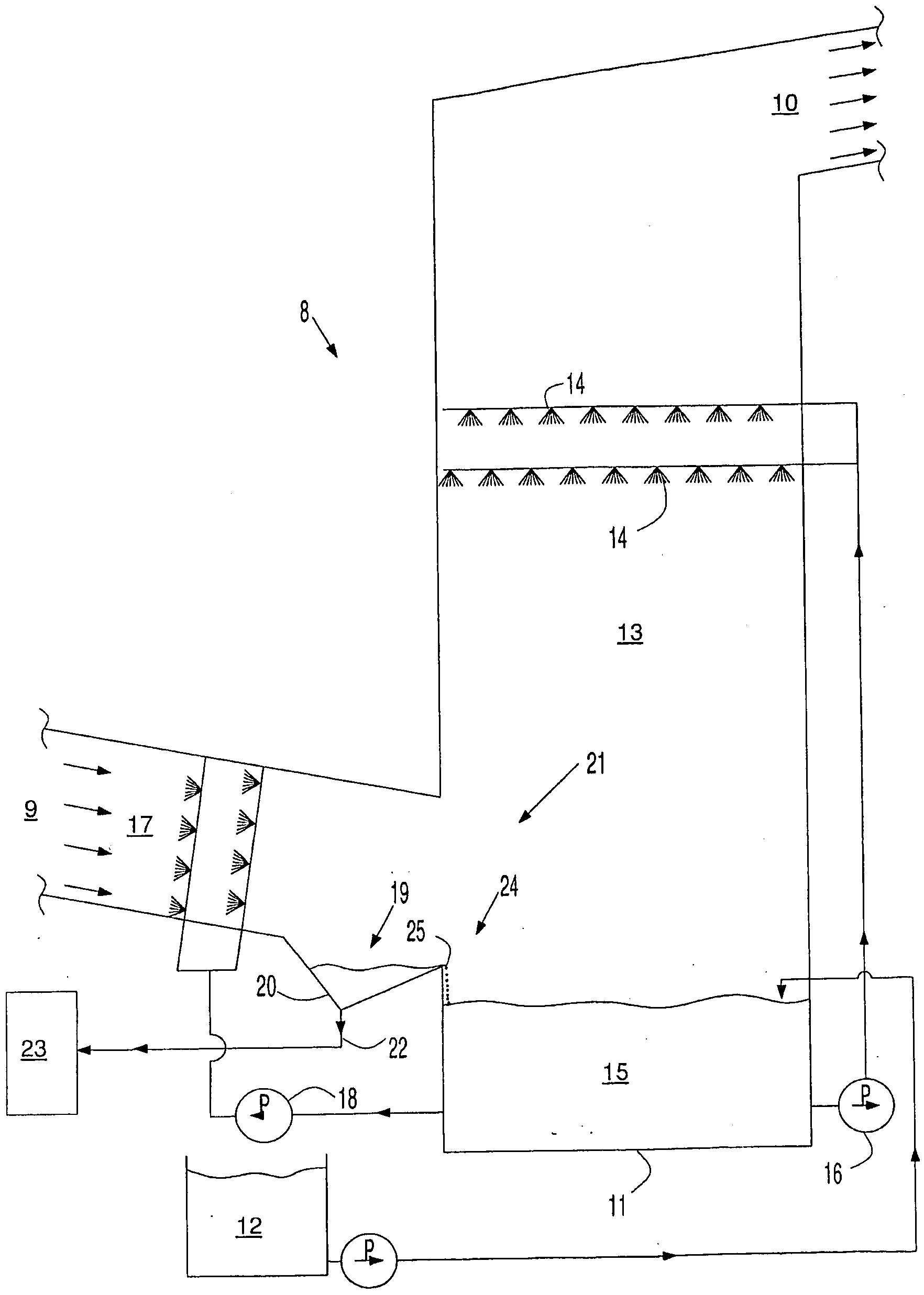
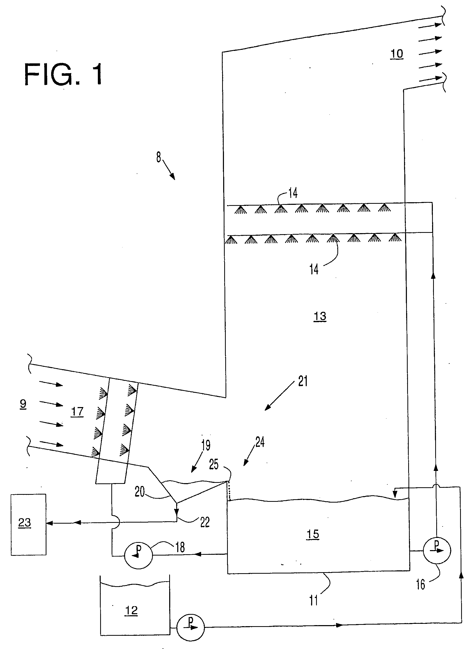
[0016]FIG. 1 shows an illustration of a flue gas desulfurization scrubbing system of the invention. The system includes a vertically elongated scrubbing tower 8, flue gas duct 9 for delivering flue gas to the scrubbing tower, and flue gas discharge duct 10 for exhausting clean flue gas from the chamber. Located at a bottom portion of the scrubbing tower is a collection section 11 into which an alkaline slurry containing SO3, Ca(OH)2, Mg(OH)2 and the like, from preparation tank 12, is pumped. Intermediate flue gas ducts 9 and 10, in a scrubbing chamber 13 are located sprayers 14, or the like, for delivering a scrubbing slurry 15 containing MgSO3, CA(OH)2, Mg(OH)2 or like reactants in a suitable form for combining with SO3, SO2, HCl or other flue gas contaminants to remove them from the flue gas prior to exhausting the flue gas to the atmosphere. The reactants are delivered to the sprayers with use of pump 16. Slurry reaction products resulting from the chemical reactions of the scrub...
PUM
| Property | Measurement | Unit |
|---|---|---|
| Gravity | aaaaa | aaaaa |
Abstract
Description
Claims
Application Information
 - R&D Engineer
- R&D Manager
- IP Professional
- Industry Leading Data Capabilities
- Powerful AI technology
- Patent DNA Extraction
Browse by: Latest US Patents, China's latest patents, Technical Efficacy Thesaurus, Application Domain, Technology Topic.
© 2024 PatSnap. All rights reserved.Legal|Privacy policy|Modern Slavery Act Transparency Statement|Sitemap