
Electrode-membrane-frame assembly for fuel cell, polyelectrolyte fuel cell and manufacturing method therefor

a fuel cell and electrodemembrane technology, applied in the field of solid polyelectrolyte fuel cells, can solve the problems of affecting the compactness of the fuel cell constituted by stacking a plurality of electric cell modules, and the comparatively expensive mea member, so as to improve the yield, the effect of improving the yield

Active Publication Date: 2008-12-11
PANASONIC CORP
View PDF12 Cites 44 Cited by
  • Summary
  • Abstract
  • Description
  • Claims
  • Application Information

AI Technical Summary

Benefits of technology

[0010]Accordingly, it is an object of the present invention to improve the above issues and provide an electrode-membrane-frame assembly capable of achieving high yield in manufacturing a solid polyelectrolyte fuel cell and a manufacturing method therefor as well as a polyelectrolyte fuel cell having an electrode-membrane-frame assembly and a manufacturing method therefor.
[0011]A further object of the invention is to provide an electrode-membrane-frame assembly for a fuel cell capable of achieving reliable sealing in an electric cell module where a membrane electrode assembly is placed between one separator and a manufacturing method therefor as well as a polyelectrolyte fuel cell having an electrode-membrane-frame assembly and a manufacturing method therefor.
[0059]According to the invention, in the structure for holding the peripheral edge portion of the membrane electrode assembly by the frame body, the holding structure with the frame body of the membrane electrode assembly, i.e., the electrode-membrane-frame assembly is achieved by separating the frame body into two pieces of the first and second frame bodies and placing the peripheral edge portion of the membrane electrode assembly held between the first frame body and the second frame body. Adopting the holding structure as described above allows the yield to be improved in comparison with, for example, a case where the electrode-membrane-frame assembly is formed by injection molding for injecting a thermoplastic resin into a metal mold in a state in which the membrane electrode assembly is placed in the metal mold for forming the frame body by resin molding. That is, in the case of forming by injection molding, it becomes difficult to separate the membrane electrode assembly from the frame body after molding. Therefore, for example, when defective molding of the frame body occurs due to injection failure of the resin material or the like, the membrane electrode assembly that is an expensive member compared with the resin material is disadvantageously wasted, and it is difficult to improve the yield. In contrast to this, in the holding structure such that the membrane electrode assembly is held between the first and second frame bodies, the holding structure of the membrane electrode assembly can be achieved separately from the manufacturing (e.g., resin molding) of the first and second frame bodies themselves. In addition, the holding by the holding of the first and second frame bodies allows the holding of the membrane electrode assembly to be easily released, and the membrane electrode assembly is not wasted. Therefore, according to the invention, a structure for improving the yield in manufacturing the electrode-membrane-frame assemblies for fuel cells and a manufacturing method therefor can be provided.

Problems solved by technology

However, for example, in the structure of the gasket integrated with the MEA as represented by JP 2001-155745 A, time and labor are necessary for a process for placing a resin material to uniformly fit the material close to the peripheral edge portion of the electrode layer without excess nor deficiency in the MEA, and this is at least inappropriate for mass production.
Furthermore, in the structure of JP 2001-155745 A, manifolds of the fuel gas and the oxidizer gas fed to the MEA are formed outside the separator plates, and this therefore also causes a harmful effect that the fuel cell constituted by stacking a plurality of electric cell modules cannot be made compact.
In particular, the MEA is a comparatively expensive member, and it is demanded to achieve high yield (productivity) in fuel cell manufacturing.

Method used


Image

  • Electrode-membrane-frame assembly for fuel cell, polyelectrolyte fuel cell and manufacturing method therefor
  • Electrode-membrane-frame assembly for fuel cell, polyelectrolyte fuel cell and manufacturing method therefor
  • Electrode-membrane-frame assembly for fuel cell, polyelectrolyte fuel cell and manufacturing method therefor

Examples


first embodiment

The First Embodiment

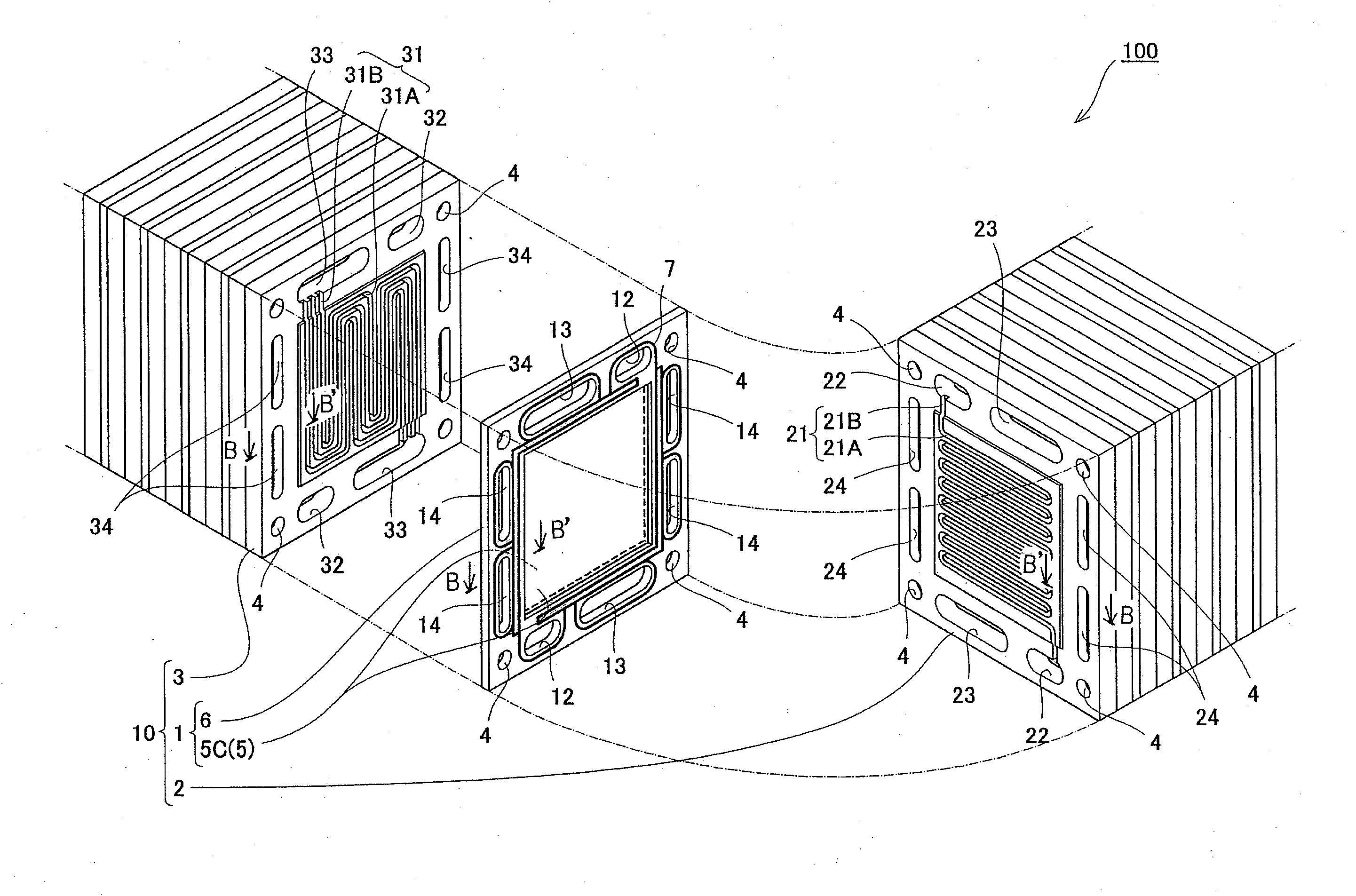
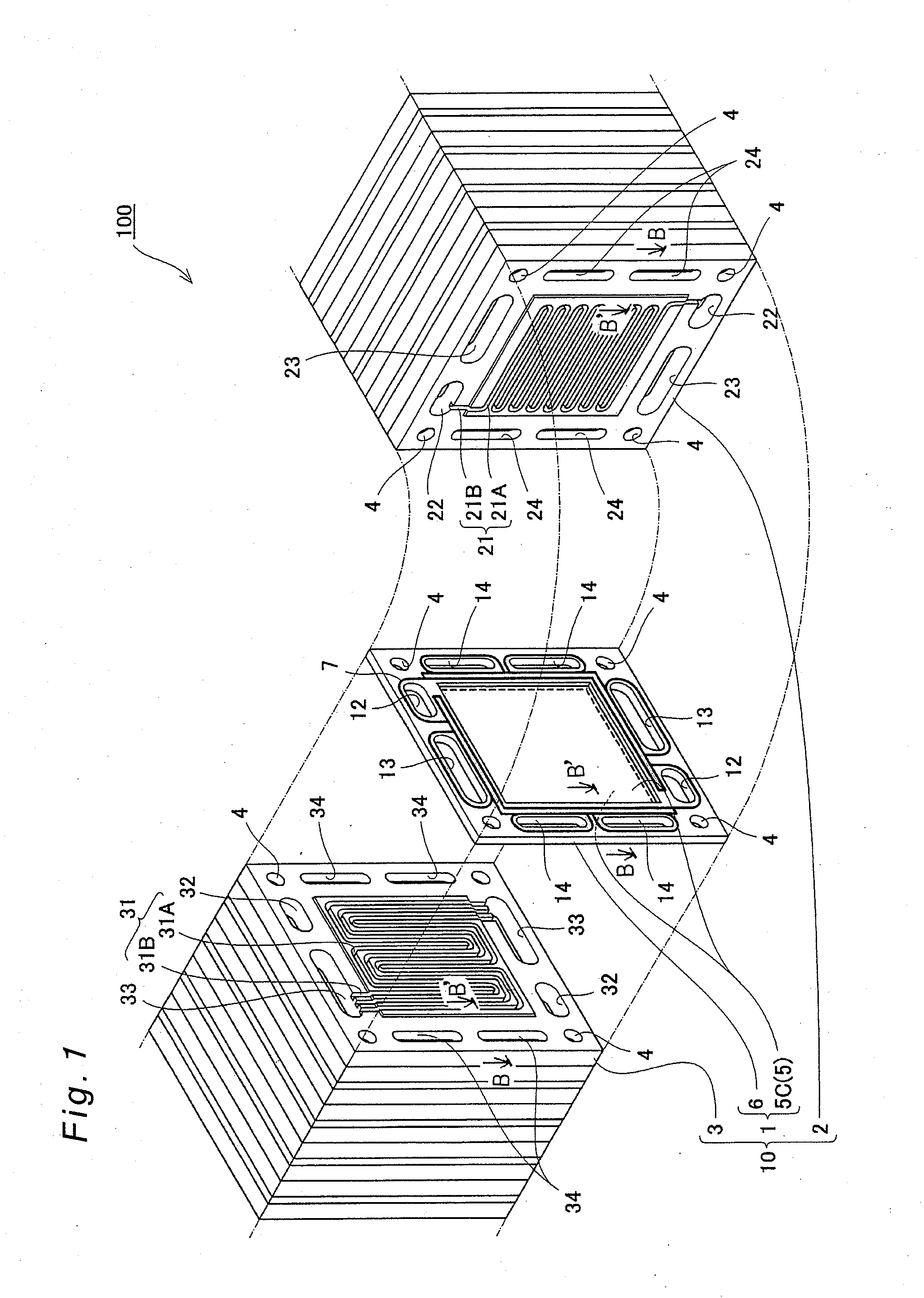
[0082]FIG. 1 is a partially exploded perspective view schematically showing the structure of a polyelectrolyte fuel cell (hereinafter referred to as “PEFC”) according to the first embodiment of the present invention.

[0083]As shown in FIG. 1, a PEFC 100 is constituted by stacking a plurality of cells (electric cell modules) 10. It is noted that a collector plate, an insulating plate and an end plate (terminal plate) are attached to the outermost layer at both ends of the cells 10, and the cells 10 are constituted by being fastened with fastening bolts that penetrate bolt holes 4 from both ends and nuts (neither is shown). In the first embodiment, sixty pieces of cells 10 are layered, and the bolts that penetrate the bolt holes 4 and the nuts are fastened with a fastening force of 10 kN. Although the structure in which the plurality of cells 10 are layered is described as an example of the first embodiment, the invention can also be applied to a case where the PEFC...

second embodiment

The Second Embodiment

[0113]The invention is not limited to the above embodiment but allowed to be implemented in various modes. For example, a schematic plan view of an electrode-membrane-frame assembly 51 according to the second embodiment of the invention is shown in FIG. 8. A top view of the first frame body is shown in FIG. 9, and a top view of the second frame body is shown in FIG. 10. Further, a sectional view taken along the line C-C′ of the electrode-membrane-frame assembly 51 of FIG. 8 is shown in FIG. 11, and a sectional view taken along the line D-D′ is shown in FIG. 12. In the electrode-membrane-frame assembly 51 of the second embodiment, same components as those of the first embodiment are designated by same reference numerals, and no description is provided therefor.

[0114]As is apparent from FIGS. 8, 9, 10, 11 and 12, the electrode-membrane-frame assembly 51 of the second embodiment differs from that of the first embodiment in that the gasket 7 does not have the double...


PUM


Abstract

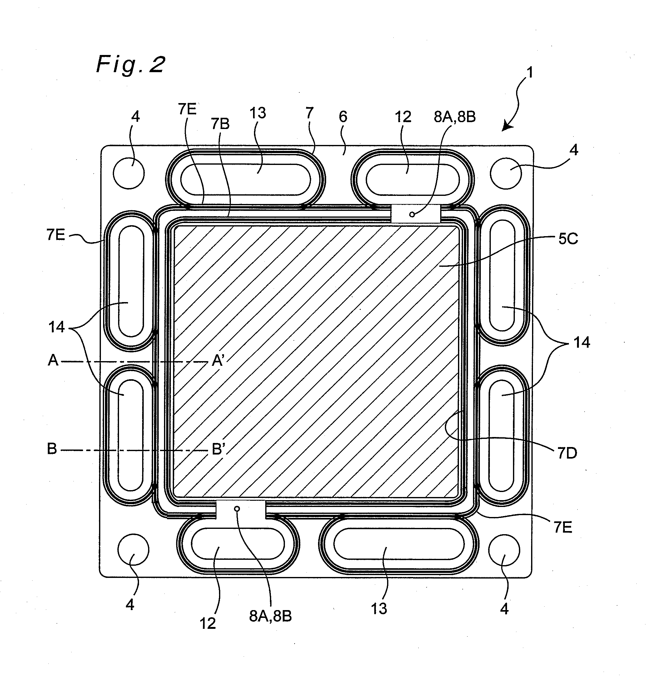
An electrode-membrane-frame assembly for a polyelectrolyte fuel cell which is held between one pair of separators and constitutes an electric cell module in the fuel cell is constituted of a membrane electrode assembly, a first frame body which has a separator-side surface on which a sealing member for sealing between the member and one separator and a membrane-side surface located on one surface of the peripheral edge portion of the membrane electrode assembly and is formed of a thermoplastic resin material, and a second frame body that has a separator-side surface on which a sealing member for sealing between the member and the other separator and a membrane-side surface located on the other surface of the peripheral edge portion of the membrane electrode assembly and is formed of a thermoplastic resin material and fitted to the first frame body holding the peripheral edge portion of the membrane electrode assembly between the second frame body and the first frame body.

Description

BACKGROUND OF THE INVENTION[0001]1. Field of the Invention[0002]The present invention relates to solid polyelectrolyte fuel cells, and, in particular, to the structure of a fuel cell electrode-membrane-frame assembly and a manufacturing method therefor.[0003]2. Description of the Related Art[0004]The solid polyelectrolyte fuel cell (hereinafter occasionally referred to as “PEFC”) is an apparatus for concurrently generating electric power and heat by electrochemically reacting a fuel gas that contains hydrogen with an oxidizer gas that contains oxygen such as air.[0005]The most typical PEFC is constructed of a polyelectrolyte membrane with a gasket of a sealing member for sealing gas at the peripheral edge portion, an electrolyte membrane-electrode assembly (hereinafter referred to as “MEA”) constituted by joining an anode to one surface of the electrolyte membrane and joining a cathode to the other surface of the electrolyte membrane, and an anode side conductive separator plate and...

Claims


Application Information

Patent Timeline
IPC IPC(8): H01M2/00H01M6/00
CPCH01M8/0276H01M2008/1095H01M8/0284H01M8/1004Y10T29/49108H01M8/0273Y02E60/521H01M8/247Y02P70/50Y02E60/50H01M8/0258H01M8/0267H01M8/2457H01M8/241H01M8/2483
Inventor KAWASHIMA, TSUTOMUKAWABATA, NORIHIKOMATSUMOTO, TOSHIHIROMURATA, ATSUSHIMORIMOTO, TAKASHI
Owner PANASONIC CORP
Learn More