

Wood planing machine including a rough-plane cutter and a fine-plane cutter
a wood planing machine and fine-plane technology, applied in the field of wood planing machines, can solve the problems of increasing operating costs, and achieve the effect of reducing operating costs and improving operating efficiency and quality
- Summary
- Abstract
- Description
- Claims
- Application Information
AI Technical Summary
Benefits of technology
Problems solved by technology
Method used
Image

Examples
Embodiment Construction
[0026]Before the present invention is described in greater detail in connection with the preferred embodiments, it should be noted that similar elements and structures are designated by like reference numerals throughout the entire disclosure.
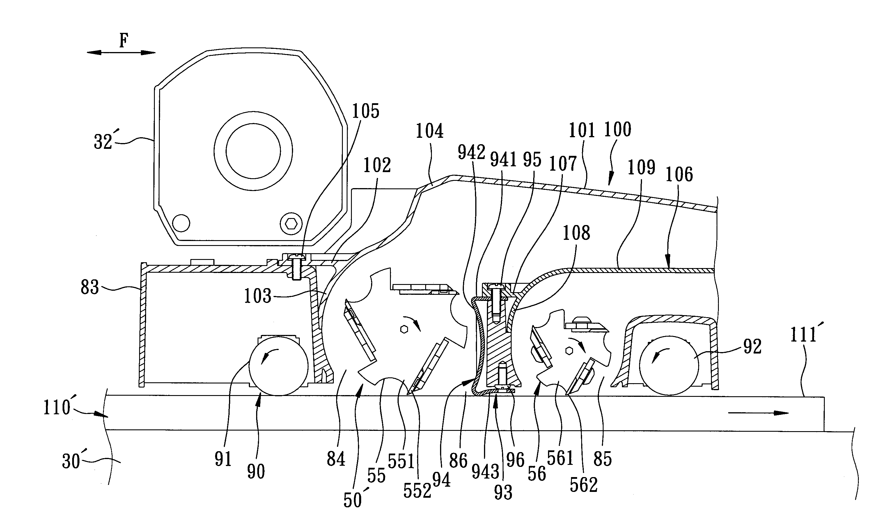
[0027]Referring to FIGS. 4, 5, and 6, the first preferred embodiment of a wood planing machine according to this invention includes a base 30, four guide posts 31 fixed on the base 30, a mounting seat 40 sleeved movably on the guide posts 31, a motor 32 disposed on the mounting seat 40, a driving unit 33 for driving the mounting seat 40 to move vertically relative to the base 30, a speed reduction unit 34 disposed on a left side of the mounting seat 40, a cutting unit 50 mounted on the mounting seat 40, a pressing unit 60, and a woodchip-guiding unit 70. The base 30 permits a wooden workpiece 8 (see FIG. 8) to be moved thereon in a front-to-rear direction (F).
[0028]Since the base 30, the guide posts 31, the motor 32, and the driving unit 33 are...
PUM
 Abstract
Description
Claims
Application Information