Engine driven welding machine
- Summary
- Abstract
- Description
- Claims
- Application Information
AI Technical Summary
Benefits of technology
Problems solved by technology
Method used
Image
Examples
embodiment 1
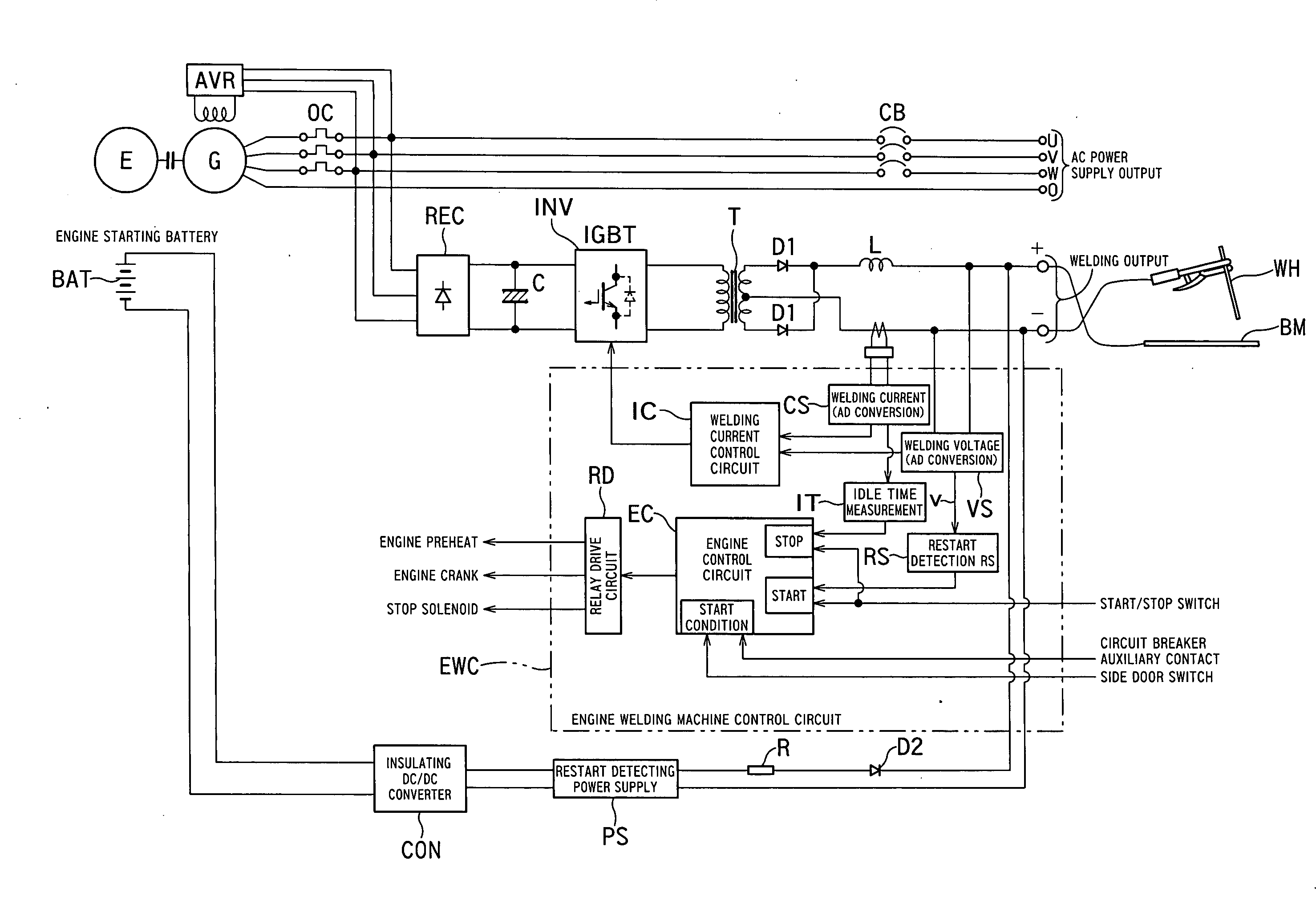
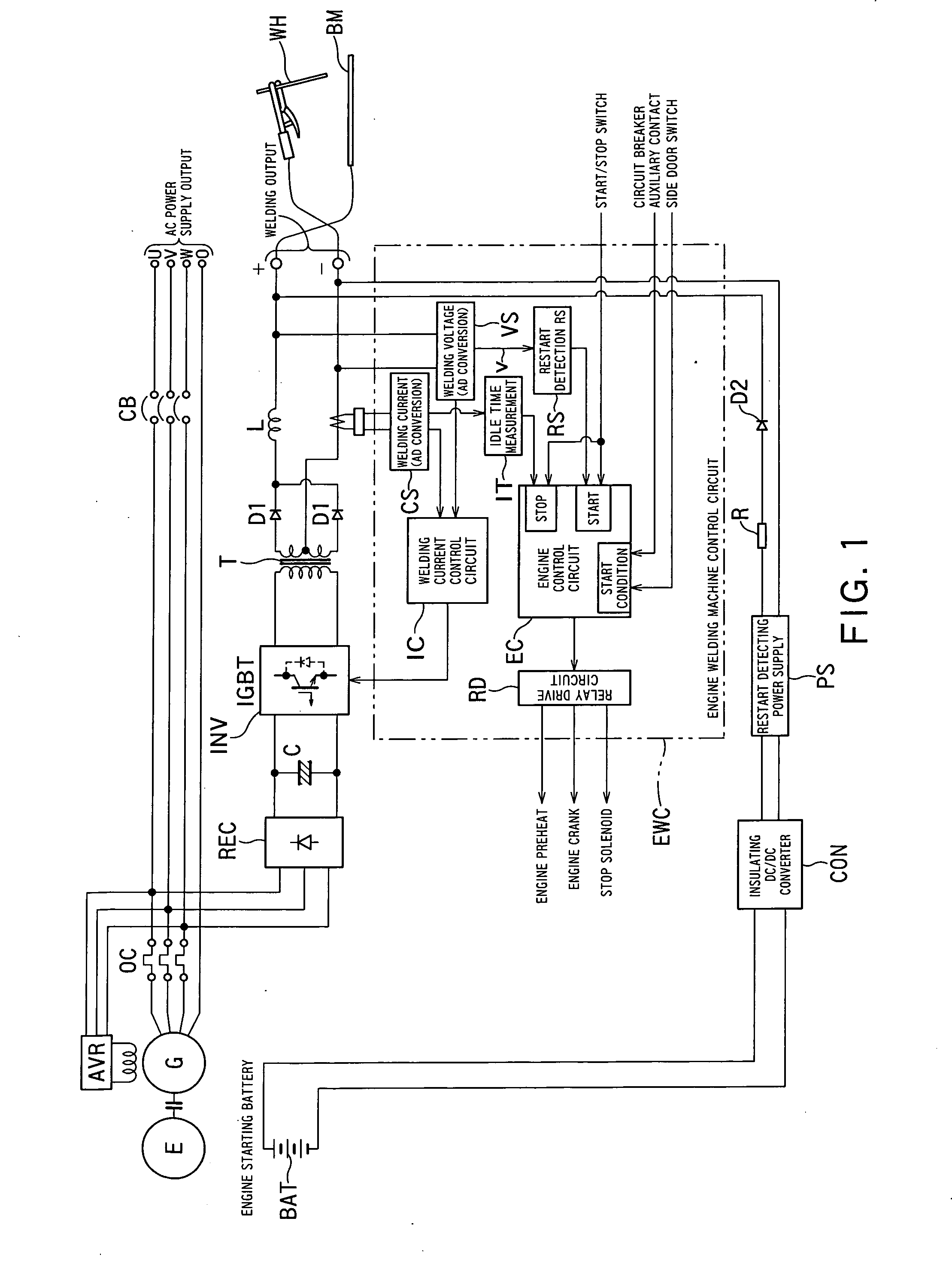
[0024]FIG. 1 is a block diagram showing a circuit configuration of an embodiment 1 of the present invention. The embodiment 1 is applied to a welding machine which supplies an alternating-current power supply output and welding output by driving a welding generator G by an engine E as shown in FIG. 1.
[0025]The welding generator G takes out the output controlled by an automatic voltage regulator AVR via an over current relay OC and divides it into two, and supplies one to output terminals U, V, W and O through a circuit breaker CB, and supplies the other one to output terminals + and − by subjecting it to DC-AC conversion and AC-DC conversion after a rectifying circuit REC and welding current control.
[0026]The rectified output of the rectifying circuit REC is given to an inverter INV through a capacitor C and subjected to AC conversion, then is given to the output terminals + and − as direct-current output via a high-frequency transformer T, rectifiers D1 and D1 and a direct-current ...
embodiment 2
[0053]FIG. 5 is a block diagram showing the configuration of embodiment 2 of the present invention. The welding machine has a single-phase auxiliary receptacle AC2 which is mainly used for a grinder operation, in addition to the welding output terminals (+, −) and the three-phase alternating-current output terminals AC1 (U, V, W, O), so as to operate the engine in accordance with the load state of each of the terminals. The single-phase auxiliary receptacle AC2 is supplied with single-phase output which is taken out from a three-phase alternating-current output line.
[0054]FIG. 6 is a flowchart showing an operational action of embodiment 2 shown in FIG. 5. The welding machine in a normal operating state is shifted to a low-speed idle operation state or stopped by performing operation control of the engine in accordance with the load state (welding load, alternating current load) and the like.
[0055]If the engine driven welding machine is under operation now, the presence or absence of...
embodiment 3
[0058]FIG. 7 is a block diagram showing a configuration of embodiment 3 of the present invention. Embodiment 3 differs from the configuration of embodiment 1 shown in FIG. 1 in the point that an engine driven welding machine under description is provided with the single-phase auxiliary receptacle AC2 which uses part of the output of the three-phase alternating-current output terminal AC1 as in embodiment 2.
[0059]Further, the different point from embodiment 2 is that not only a restart signal can be formed by short-circuiting / opening of the welding output terminals, but also a restart signal can be formed by turning on and off the switch of a grinder which is connected to the single-phase auxiliary receptacle AC2. For this purpose, an engine welding machine control circuit EWC is configured to include a voltage detector VD which detects the voltage of the single-auxiliary receptacle AC2 and to give the detection output to the restart detecting circuit RS.
[0060]Accompanying this, in o...
PUM
| Property | Measurement | Unit |
|---|---|---|
| Electric potential / voltage | aaaaa | aaaaa |
Abstract
Description
Claims
Application Information
 - R&D
- Intellectual Property
- Life Sciences
- Materials
- Tech Scout
- Unparalleled Data Quality
- Higher Quality Content
- 60% Fewer Hallucinations
Browse by: Latest US Patents, China's latest patents, Technical Efficacy Thesaurus, Application Domain, Technology Topic, Popular Technical Reports.
© 2025 PatSnap. All rights reserved.Legal|Privacy policy|Modern Slavery Act Transparency Statement|Sitemap|About US| Contact US: help@patsnap.com


