Hinged blade device to convert the natural flow or ocean or river current or ocean waves to rotational mechanical motion for power generation

a technology of rotating blades and power generation, which is applied in the direction of electric generator control, renewable energy generation, greenhouse gas reduction, etc., can solve the problems of large infrastructures such as power generation stations or large wind turbines, cost-competitive renewable energy sources, and increased natural gas and coal costs. to achieve the effect of maximizing power generation

Inactive Publication Date: 2008-12-18
LIN CHENG S
View PDF1 Cites 41 Cited by
  • Summary
  • Abstract
  • Description
  • Claims
  • Application Information

AI Technical Summary

Benefits of technology

[0027]The present invention is a device to harness useful rotating mechanical power from the natural movement of wind, river or ocean current, ocean wave, or tidal flow. The rotating mechanical power can be converted to electrical energy using means well known to those skilled in suc...

Problems solved by technology

Although these systems are generally feasible for extracting useful work from the natural movement of air or water, they require large infrastructures like dams and power generation stations or large wind turbines.
In spite of the difficulties in extracting useful hydroelectric power, the costs for natural gas and coal have risen to a point where renewable sources of power generation are cost-competitive.
In less developed countries, ...

Method used


Image

  • Hinged blade device to convert the natural flow or ocean or river current or ocean waves to rotational mechanical motion for power generation
  • Hinged blade device to convert the natural flow or ocean or river current or ocean waves to rotational mechanical motion for power generation
  • Hinged blade device to convert the natural flow or ocean or river current or ocean waves to rotational mechanical motion for power generation

Examples


Embodiment Construction

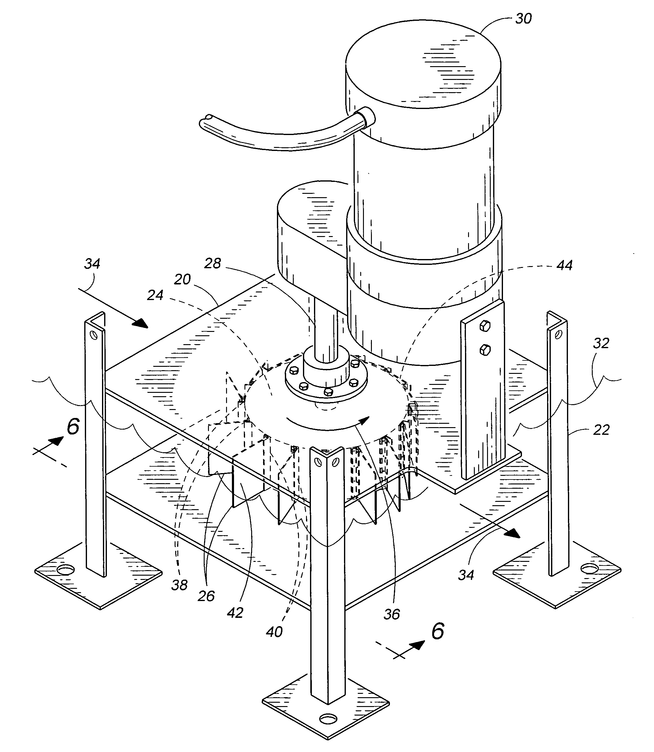
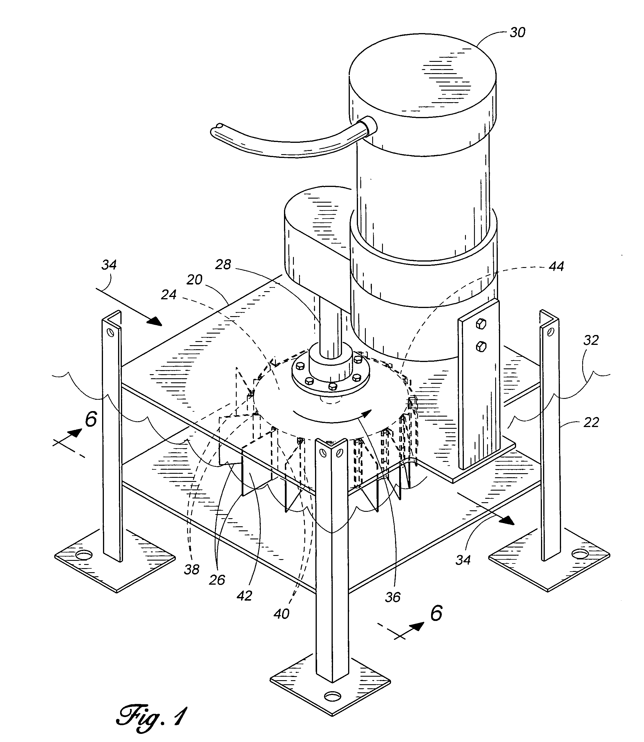
[0042]FIG. 1 illustrates the preferred embodiment of the invention. The portable power producing device 20 comprises a support structure 22, central hub 24, a plurality of blades 26, a power take off assembly 28 connected to central hub 24, further connected to an electrical generator 30. Each blade 26 is connected to central hub 24 by hinge 38. Central hub 24 is submerged in water of about level 32. The water is moving in direction 34 which causes the central hub 24 to rotate in counterclockwise direction depicted by arrow 36.

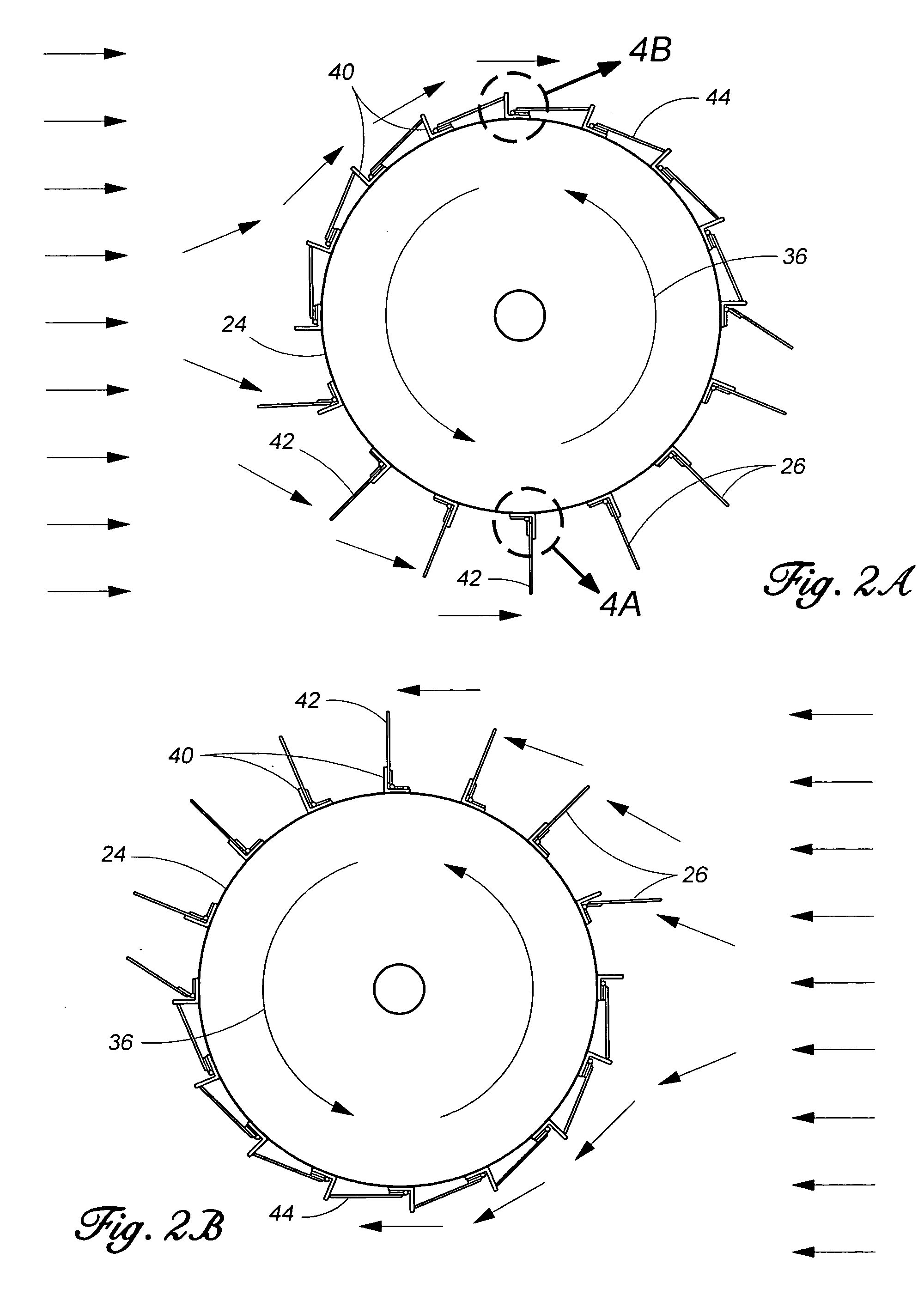
[0043]Continuing to refer to FIG. 1, the motion of the water against blades 26 causes them to rotate about the hinges 38. Every blade 26 is free to rotate about its hinge 38 within 90 degrees which is inside the limits of the blade limiter 40. Each blade 26 opens to the appropriate extent within the limits imposed by blade limiter 40 depending on the motive fluid direction and the position of the central hub 24. When a blade 26 is in its fully extended positio...


PUM


Abstract

A device and method for producing rotational mechanical power is disclosed which has a plurality of hinged blades attached to a central circular hub. The device may be used to convert the kinetic energy from the movement of the wind, ocean or river currents, or tidal flows into useful rotational mechanical power. The rotational mechanical power may be converted into electrical energy. Each of the plurality of blades are attached to the central circular hub via a hinge. Each blade is also fitted with a blade limiter to restrict its motion to no more than 90° relative range from the tangent line to the central hub at the point where the blade attaches to the hub. The hinges and blade limiters allow the blades to both present a surface automatically to the motive natural fluid and to generate the maximum torque in one side and minimum resistance torque positions in the opposite side relative to the motion of the motive stream. The resultant blades relative position creates a torque differential from one side of the central hub to the other causing the hub to rotate. The central hub will rotate in the same direction regardless of the direction of flow of the natural motive stream.

Description

CROSS-REFERENCES RELATED APPLICATIONS[0001]Not applicable.STATEMENT REGARDING FEDERALLY SPONSORED RESEARCH OR DEVELOPMENT[0002]Not applicable.MICROFICHE APPENDIX[0003]Not applicable.BACKGROUND OF THE INVENTION[0004](1) Field of the Invention[0005]The present invention relates to apparatus which convert the movement of a fluid, particularly air or water, into rotational mechanical motion for the generation of mechanical power or other useful purposes. In this invention, naturally flowing air as wind or water as tidal, creek, stream or river flow impinges upon hinged blades mounted on a central disk. The force of fluid upon the hinged blades induces torque to a central disk which causes it to rotate thereby producing useful rotational mechanical motion. The rotational mechanical motion may be transmitted to a generator to produce electricity or to another power take-off device to extract useful work.[0006]The present invention further relates to apparatus which are small and economica...

Claims


Application Information

Patent Timeline
IPC IPC(8): F03B13/00F03B7/00
CPCF03B17/065F03D3/067F05B2240/40Y02E10/28Y02E10/74Y02E10/30Y02E10/20
Inventor LIN, CHENG S.
Owner LIN CHENG S
Why Eureka
Try Eureka