
Semiconductor power device having a stacked discrete inductor structure

Active Publication Date: 2008-12-18
ALPHA & OMEGA SEMICON INC
View PDF11 Cites 69 Cited by
  • Summary
  • Abstract
  • Description
  • Claims
  • Application Information

AI Technical Summary

Benefits of technology

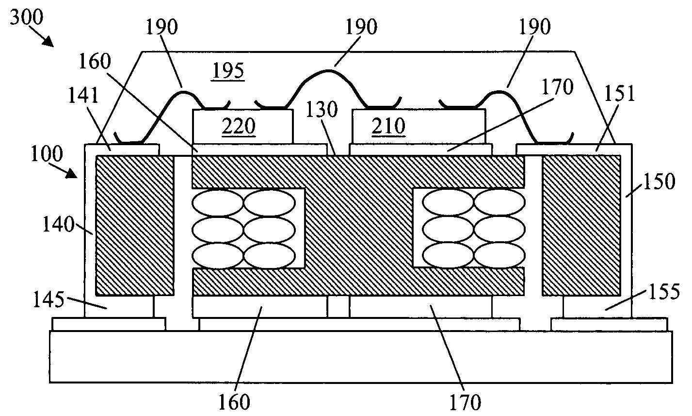
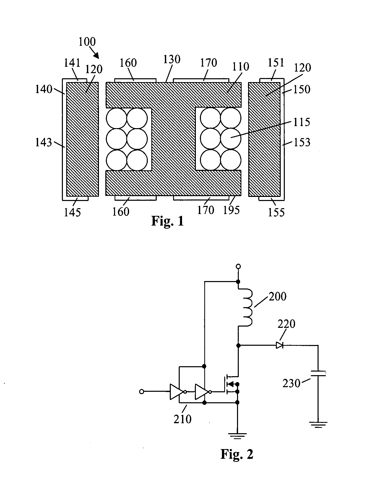
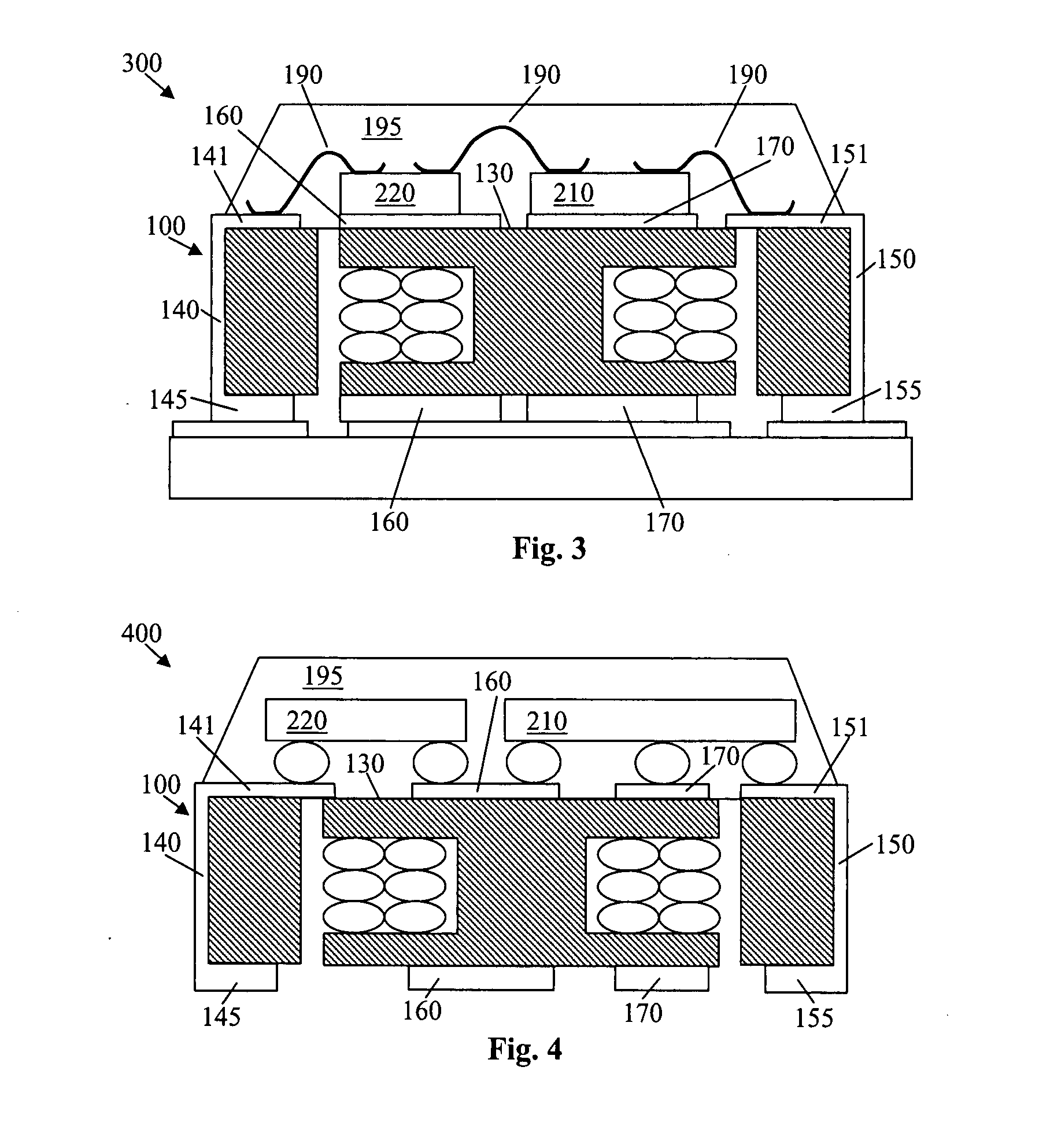
[0009]The semiconductor power device having a stacked discrete inductor structure in accordance with the invention minimizes overall assembly and packaging costs by dispensing with the need for a separate substrate or lead-frame. In one aspect of the invention, a power device includes a discrete inductor having leads electrically coupled to the inductor electrodes and wrapping around a periphery of the discrete inductor. The leads allow for the stacking and electrical connection of semiconductor components upon a top surface of the discrete inductor. Contacts and routing connections formed on the top surface and wrapping around a periphery of the discrete inductor provide additional contacts for the stacked semiconductor components. The semiconductor components may be flip chip mounted onto the discrete inductor leads and contacts and routing connections or wire bonded thereto.
[0012]In accordance with yet another aspect of the invention, a multi-layer spiral style low-profile and small dimension discrete inductor has patterned electrodes formed thereon to route electrical signals from a stacked integrated circuit or circuits mounted on a surface of the discrete inductor by flip chip mounting techniques. The package can be flip chip mounted onto a printed circuit board or system level board with the mounted integrated circuit or circuits in contact with the printed circuit board or system level board for better heat sinking.

Problems solved by technology

Power converters implemented in this way suffer the disadvantages of having higher component cost and of requiring more printed circuit board space.
The package disadvantageously uses valuable printed circuit board space.
This results in a higher product cost since the cost of the Power-IC, on a per unit area basis, is much higher than that of the inductor.
This also results in a large overall package size.
Furthermore, complex processing is necessary in order to fabricate the planar magnetic layers and the overall inductor structure having appropriate electrical characteristics.

Method used


Image

  • Semiconductor power device having a stacked discrete inductor structure
  • Semiconductor power device having a stacked discrete inductor structure
  • Semiconductor power device having a stacked discrete inductor structure

Examples


Embodiment Construction

[0035]The present invention will now be described in detail with reference to the drawings, which are provided as illustrative examples of the invention so as to enable those skilled in the art to practice the invention. Notably, the figures and examples below are not meant to limit the scope of the present invention. Where certain elements of the present invention can be partially or fully implemented using known components, only those portions of such known components that are necessary for an understanding of the present invention will be described, and detailed descriptions of other portions of such known components will be omitted so as not to obscure the invention. Further, the present invention encompasses present and future known equivalents to the components referred to herein by way of illustration.

[0036]The semiconductor power device having a stacked discrete inductor structure of the invention provides a device that maximizes the overall device performance by combining t...


PUM


Abstract

A power device includes a discrete inductor having contacts formed on a first surface of the discrete inductor and at least one semiconductor component mounted on the first surface of the discrete inductor and coupled to the contacts. The discrete inductor further includes contacts formed on a second surface opposite the first surface and routing connections connecting the first surface contacts to corresponding second surface contacts. The semiconductor components may be flip chip mounted onto the discrete inductor contacts or wire bonded thereto.

Description

BACKGROUND OF THE INVENTION[0001]1. Field of the Invention[0002]The present invention generally relates to semiconductor power devices and more particularly to a semiconductor power device having a stacked discrete inductor structure wherein at least one semiconductor component is stacked on, and electrically coupled to electrodes of, a discrete inductor. Routing connections formed on the discrete inductor provide additional contacts to the at least one semiconductor component.[0003]2. Description of Related Art[0004]It is well known to include a discrete inductor on the printed circuit board when implementing a power converter circuit. For example, the Analogic™TECH 1 MHz 400 mA Step-Down Converter (AAT1143) requires the use of a discrete inductor. Power converters implemented in this way suffer the disadvantages of having higher component cost and of requiring more printed circuit board space.[0005]Discrete inductors co-packaged with power ICs and other components are also well kn...

Claims


Application Information

Patent Timeline
IPC IPC(8): G05F1/62H01F27/06H01L23/48
CPCH01F17/0013H01F17/045H01F27/292H01F27/40H01F2007/1822H01L23/645H01L24/49H01L24/81H01L24/85H01L25/072H01L2224/05553H01L2224/16225H01L2224/48091H01L2224/48137H01L2224/48472H01L2224/49111H01L2224/49171H01L2224/81801H01L2924/01013H01L2924/01015H01L2924/01027H01L2924/01028H01L2924/01029H01L2924/01033H01L2924/01047H01L2924/0105H01L2924/01078H01L2924/01079H01L2924/01082H01L2924/14H01L2924/15173H01L2924/15174H01L2924/1532H01L2924/19041H01L2924/19042H01L2924/19107H01L2924/30107H01L24/48H01L2924/01006H01L2924/014H01L2224/85H01L2224/45147H01L2224/48799H01L2224/0401H01L2924/1306H01L2924/1461H01L2924/12032H01L2224/16235H01L2924/00014H01L2924/00H01L2924/181H01L24/45H01L2924/10162H01L2924/00012
Inventor HEBERT, FRANCOIS
Owner ALPHA & OMEGA SEMICON INC
Learn More