
Sequential brake light system

a brake light and sequence technology, applied in the field of sequential brake light systems, can solve the problems of insufficient time required to correlate and assess this information, collision between vehicles, and driving too serious to be based on one's decision, so as to reduce the number of these types of accidents

Inactive Publication Date: 2008-12-18
MORALES CHARLES J
View PDF5 Cites 35 Cited by
  • Summary
  • Abstract
  • Description
  • Claims
  • Application Information

AI Technical Summary

Benefits of technology

[0013]A speed sensor is connected to a logic circuit which, in turn, is connected to a vehicle computer system. The system of the invention is programmed to be activated at predetermined speeds, with the flashing motion of the lights deactivated once the vehicle has slowed to near stop. For example, the brake lighting system of the invention may be programmed to flash whenever a driver was traveling at speeds greater than 20 or 25 or other specific and selected number of miles per hour, thus affording drivers in other vehicles ample time to slow their own car, should the sequential brake light system begin to flash.
[0016]As noted, many accidents are caused by drivers not being aware of another driver's intent when braking and the sequential brake light system of the invention can greatly reduce the number of these types of accidents. The safety benefits afforded by the invention could be beneficially used on cars, trucks, utility vehicles, and other road vehicles.

Problems solved by technology

However, as the number of roads, cars and drivers multiplied, so did the number of automobile accidents, until the point that the Federal Government determined a need existed to require automobile manufacturers to begin designing safer cars.
While there is little dispute that brake lights are a crucial safety element of any vehicle, there are drawbacks associated with their use.
The time required to correlate and assess this information may not always be enough to avoid an accident, particularly in emergency or panic braking situations which can, and do, unexpectedly arise.
As a result of this misinterpretation of intent, a collision between the vehicles may occur.
Driving is too serious to be basing one's decisions on interpretation of ambiguous signals.

Method used


Image

  • Sequential brake light system
  • Sequential brake light system
  • Sequential brake light system

Examples


Embodiment Construction

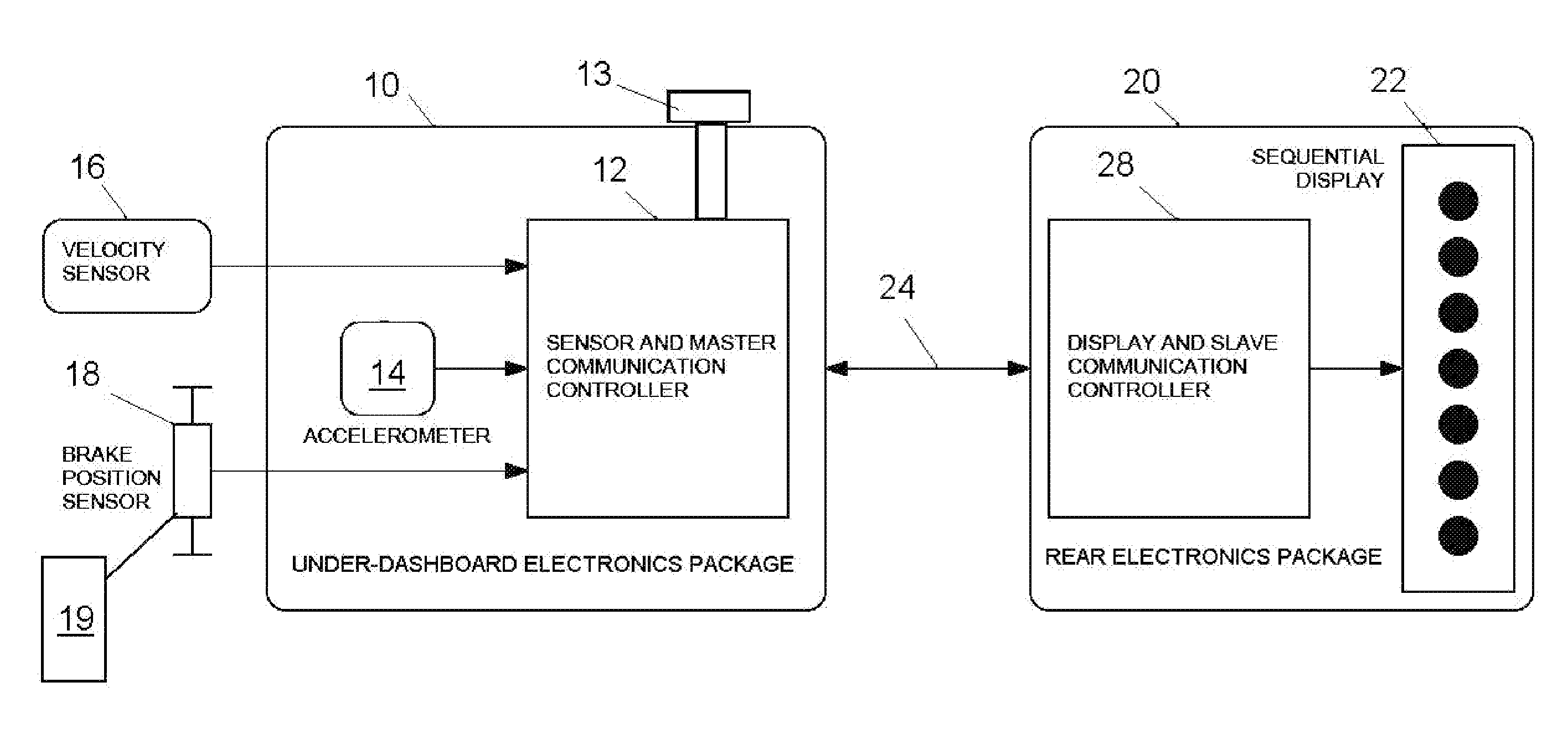
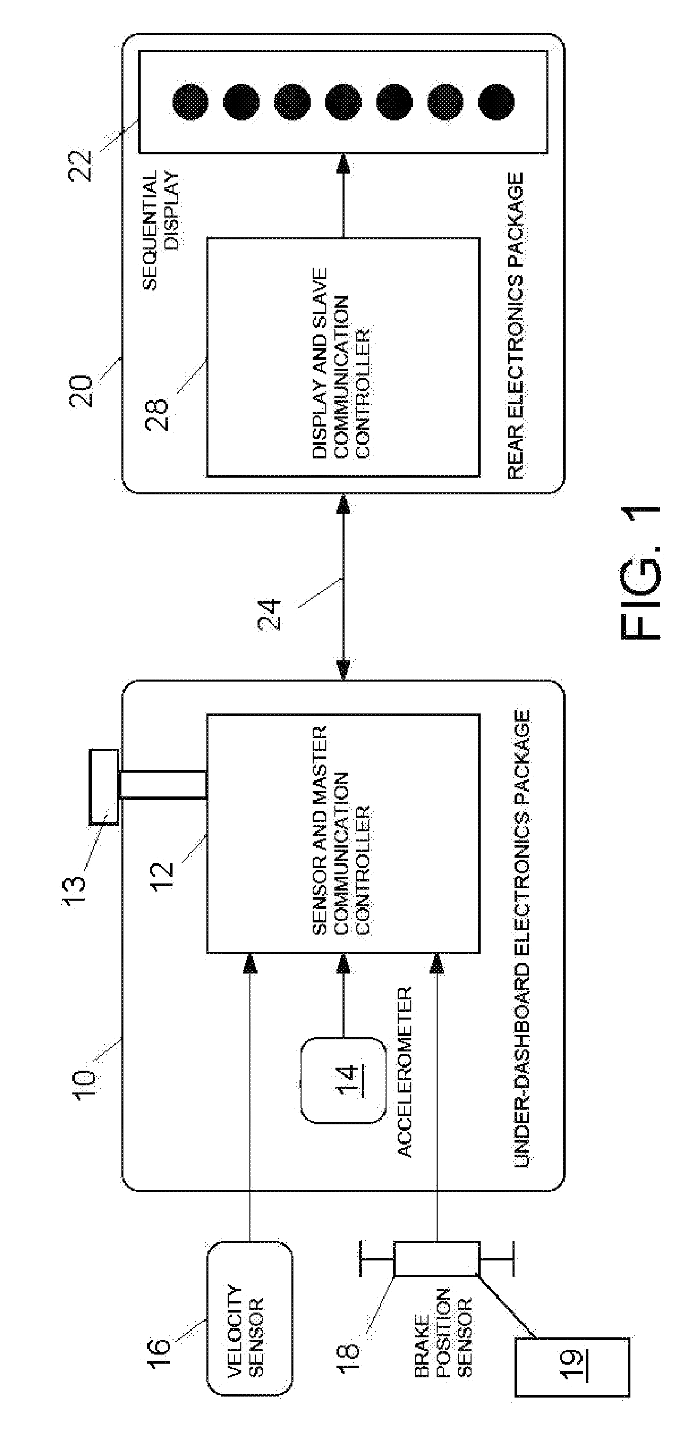
[0026]Referring now to the drawings, FIG. 1 illustrates a sequential brake light system of the invention for automotive or other road vehicles. The system comprises a speed or velocity sensing mechanism or device 16, that is wires to, or is independent of the speedometer that is provided on all road-legal, road vehicles. For vehicles having a compatible speedometer, the existing speedometer of the vehicle can be wired to the system and the speed sensor 16.

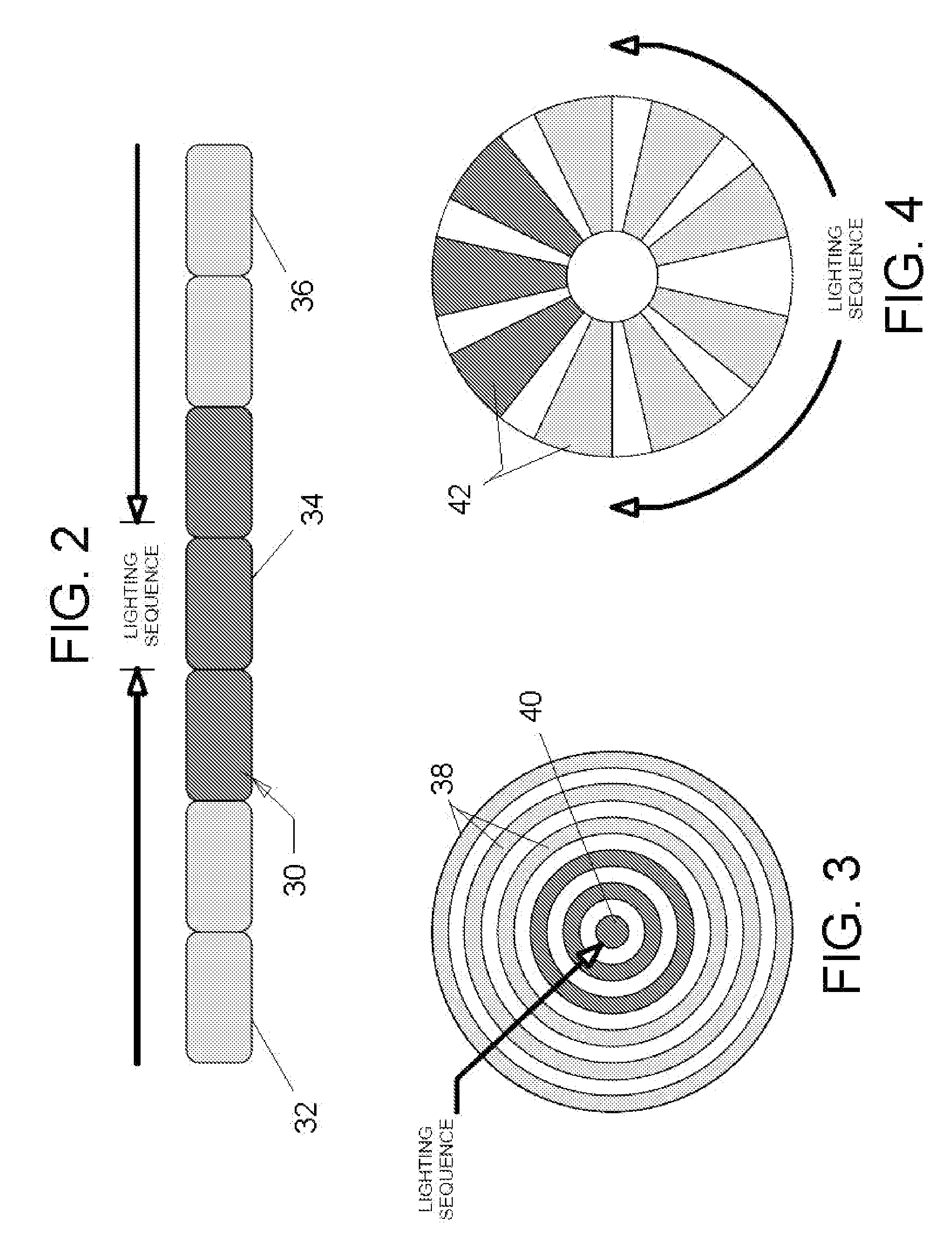
[0027]The system of the intention includes a third brake light array 22, made up of a plurality of individual red lights in a series such as a linear series of lights 30, 32 and 34 in FIG. 2, or concentric lights 38 and 40 in FIG. 3, or radial lights 42 that are circumferentially distributed around a circle in FIG. 4. The array 22 is mounted on or behind the rear window or near either or both tail lights of the road vehicle, or at any location on the vehicle, so that the array 22 is visible to the driver of a trailing vehicle on th...


PUM


Abstract

A sequential brake light system for road vehicles has a brake light array of plural lights in a linear, concentric or radial series. A master and slave controllers are connected to the array for lighting the lights in sequence and repeatedly at a rate that is proportional to a deceleration of the vehicle upon braking. A speed sensor senses the instantaneous vehicle speed and deactivates the master controller if the speed is below a threshold value so that the array is not powered in stop-and-go traffic. A brake position sensor senses a position of the vehicle brake pedal and an accelerometer measures deceleration of the vehicle, so that the master controller receives signals corresponding to the instantaneous speed of the vehicle, a signal corresponding to the position of the brake pedal and a signal corresponding to the deceleration of the road vehicle for properly warning a trailing drive of the braking condition of the road vehicle.

Description

CROSS REFERENCE TO RELATED APPLICATION[0001]This application claims priority benefits under 35 U.S.C. §119(e), on U.S. provisional patent application 60 / 934,620 file Jun. 15, 2007, which provisional application is incorporated here by reference.FIELD AND BACKGROUND OF THE INVENTION[0002]The present invention relates generally to the field of automotive and other road vehicle signals, and in particular to a new and useful apparatus and method of signaling that a road vehicle is about to slow down or stop, to trailing vehicles on the road.[0003]Everyday, millions of Americans climb into their road vehicles including cars, SUVs, trucks, minivans and the like, and make their way across the highways and byways of this great land. Whether a retired couple embarking on a cross country journey, a college coed enduring a long commute to school, or a busy homemaker driving a few blocks to the neighborhood grocer, automobiles offer consumers a simple way in which to get from one place to anoth...

Claims


Application Information

Patent Timeline
Patent Type & Authority Applications(United States)
IPC IPC(8): B60Q1/44
CPCB60Q1/444
Inventor MORALES, CHARLES J.
Owner MORALES CHARLES J
Learn More