Sensor node and sensor network system

Active Publication Date: 2008-12-18
HITACHI LTD
View PDF10 Cites 77 Cited by
  • Summary
  • Abstract
  • Description
  • Claims
  • Application Information

AI Technical Summary

Benefits of technology

[0022]According to this invention, it is possible to surely collect the sensing data for a long period without any loss by compressing and then storing the sensing data, which cannot be wirelessly transmitted, in the non-volatile storage unit.
[0023]Moreover, since the electric power is supplied to the non-volatile storage unit only when an access thereto is carried out, it is possible to prevent a leak current or the like in a standby state, thereby preventing the battery from being consumed.
[0024]Moreover, the data compression is carried out by obtaining a difference between data, and then, encoding the difference. Biological information (such as acceleration), which is activity data of a living organism, does not exhibit a sudden temporal change, and mostly represents

Problems solved by technology

However, as a first problem, the above-mentioned conventional compact sensor node has a limit in available electric power, and thus, the availability of the communication extremely frequently changes depending on a radio wave environment and a state of a user.
Especially, for a compact sensor node, a usable antenna is limited.
If a person uses the sensor node under such a condition in daily life, due to a posture of the person or a surrounding environment, the wireless communication frequently fails even at a communicable d

Method used


Image

  • Sensor node and sensor network system
  • Sensor node and sensor network system
  • Sensor node and sensor network system

Examples


first embodiment

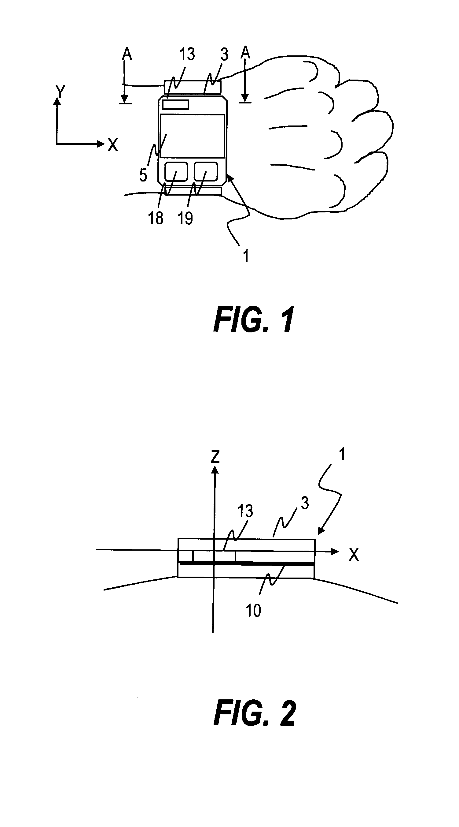
[0062]FIG. 1 illustrates a first embodiment, and is a front view of a sensor node 1 of a wrist watch (or bracelet) type, to which this invention is applied, and FIG. 2 is a cross sectional view made on a plane and in a direction indicated by arrows A in FIG. 1.

[0063]In FIG. 1, the sensor node 1 includes a case 3 which stores an antenna 13, a sensor, and a control unit, and a band used for wearing the case 3 on the arm of the human body. On the case 3, a liquid crystal display (LCD) 5 used for displaying information, and button switches 18 and 19 used for executing specific functions programmed in advance are provided. Moreover, the LCD 5 can be configured as a touch panel for selecting items displayed on the LCD 5. The antenna 13 is shown in FIG. 1 for illustrating a position thereof, but actually, the antenna 13 is arranged on a circuit board 10 disposed inside the case 3 as shown in FIG. 2. In FIG. 2, a surface of the circuit board 10 on which the antenna 13 is mounted is the oppo...

second embodiment

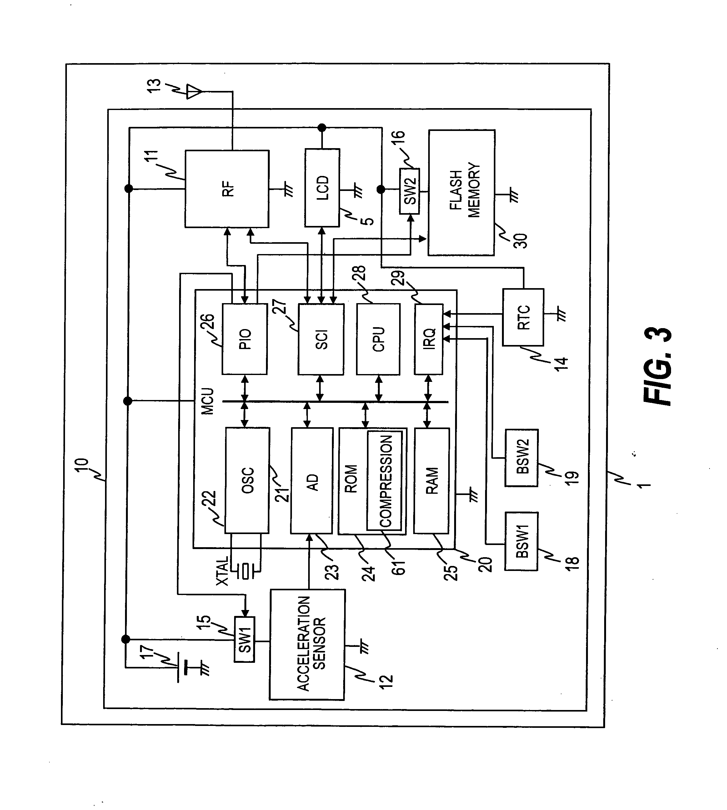
[0165]FIG. 28 illustrates a block diagram of an electronic circuit mounted on the circuit board 10 of the sensor node 1 according to a second embodiment of the present invention, and a pulse wave sensor 19 shown in a lower left section of FIG. 28 is added to the configuration of the first embodiment of the present invention. The second embodiment includes the pulse wave sensor 119 in addition to the acceleration sensor 12 according to the first embodiment, and the other configuration thereof is the same as the configuration of the first embodiment of the present invention.

[0166]This pulse wave sensor 119 employs an infrared light emitting diode as a light emitting element LD1, and a phototransistor as a light receiving element PD1. It should be noted that a photodiode may be used as the light receiving element PD1 in place of the phototransistor. On a rear surface of the case 3, the light emitting element LD1 and the light receiving element PD1 are exposed, and can oppose the skin o...


PUM


Abstract

Provided is a sensor node including: a sensor for measuring biological information; a CPU for acquiring data by driving the sensor; a wireless communication unit for transmitting the data acquired by the CPU; a battery for supplying the control unit, the wireless communication unit, and the sensor with electric power; a RAM for storing the data; a compression unit for compressing the data stored in the RAM when the wireless communication unit cannot carry out the transmission; and a flash memory for storing the compressed data, thereby storing as much sensing data as possible on the sensor node, which is limited in resources, and preventing loss of the sensing data.

Description

CLAIM OF PRIORITY[0001]The present application claims priority from Japanese application P2007-158474 filed on Jun. 15, 2007, the content of which is hereby incorporated by reference into this application.BACKGROUND OF THE INVENTION[0002]This invention relates to a storage for large volume waveform data and a data compression technology for the waveform data used for a compact wireless biological information terminal, and the like.[0003]Recently, for medical practices, health management, and the like at hospitals, nursing and care facilities, and households, terminals which wirelessly receive information from biological information sensors (sensors for sensing ECG, pulse, blood pressure, acceleration, and the like) have been developed.[0004]For example, JP 2005-352881A discloses a behavior management system which measures changes in position and posture of respective parts of a body based on sensors attached to the respective parts of the body, and transmits the measured data via a ...

Claims


Application Information

Patent Timeline
IPC IPC(8): H04Q7/00H04W84/18
CPCA61B5/0002A61B5/02438A61B5/11A61B2560/045A61B2562/0219H04W84/18A61B5/7232
Inventor TANAKA, TAKESHIYAMASHITA, SHUNZOAIKI, KIYOSHI
Owner HITACHI LTD
Why Eureka
Try Eureka