Microlithographic projection exposure apparatus and measuring device for a projection lens

a technology of exposure apparatus and exposure lens, which is applied in the field of microlithographic projection exposure apparatus, can solve the problems of distortion of wave fronts passing through, fluctuations in the refractive index of immersion liquid, and unsatisfactory intensity fluctuations in the image plane, etc., and achieves efficient heat dissipation and high thermal conductivity.

Inactive Publication Date: 2008-12-18
CARL ZEISS SMT GMBH
View PDF99 Cites 16 Cited by
  • Summary
  • Abstract
  • Description
  • Claims
  • Application Information

AI Technical Summary

Benefits of technology

[0018]It is therefore the object of the invention to improve a projection exposure apparatus, and a measuring device for the optical measurement of projection lenses, such that imaging defects resulting from inhomogeneities of the refractive index within the immersion liquid are reduced.

Problems solved by technology

A difficulty with the immersion operation of projection exposure apparatuses is to keep the optical characteristics of the immersion liquid constant, at least where the liquid is exposed to the projection light.
Local fluctuations in the absorption, as can be produced, for example, by impurities, lead to undesired intensity fluctuations in the image plane.
Local fluctuations in the refractive index of the immersion liquid have an especially detrimental effect, since such fluctuations directly impair the imaging characteristics of the projection exposure apparatus.
If the refractive index of the immersion liquid is inhomogeneous within the volume of the immersion liquid exposed to the projection light, this causes distortions of the wave fronts passing through the immersion space.
Moreover, temperature fluctuations within the immersion liquid not only cause fluctuations of refractive index, but can also cause adjacent optical elements, in particular the last optical element of the projection lens on the image side, to be heated unevenly and therefore to be deformed in a manner that can hardly be corrected.
However, the homogenization of temperature distribution that can be achieved in this way is frequently not sufficient.
Relatively high flow velocities, which may lead to disturbing vibrations, are usually required.
In addition, high flow velocities promote the formation of gas bubbles which can also adversely affect the imaging properties.
Moreover, similar difficulties also arise in measuring devices with which the imaging characteristics of such projection lenses can be determined.
Because of the extremely high demands on the measuring accuracy of such devices, inhomogeneities of refractive index within the immersion liquid cannot be tolerated.

Method used


Image

  • Microlithographic projection exposure apparatus and measuring device for a projection lens
  • Microlithographic projection exposure apparatus and measuring device for a projection lens
  • Microlithographic projection exposure apparatus and measuring device for a projection lens

Examples


Embodiment Construction

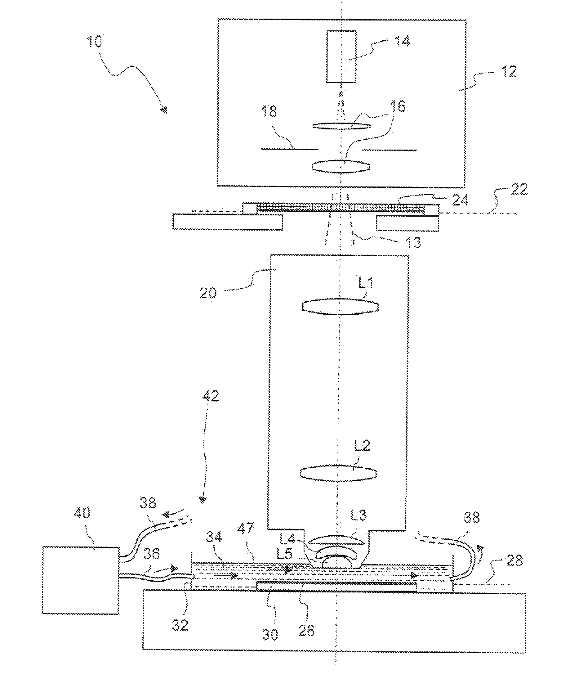
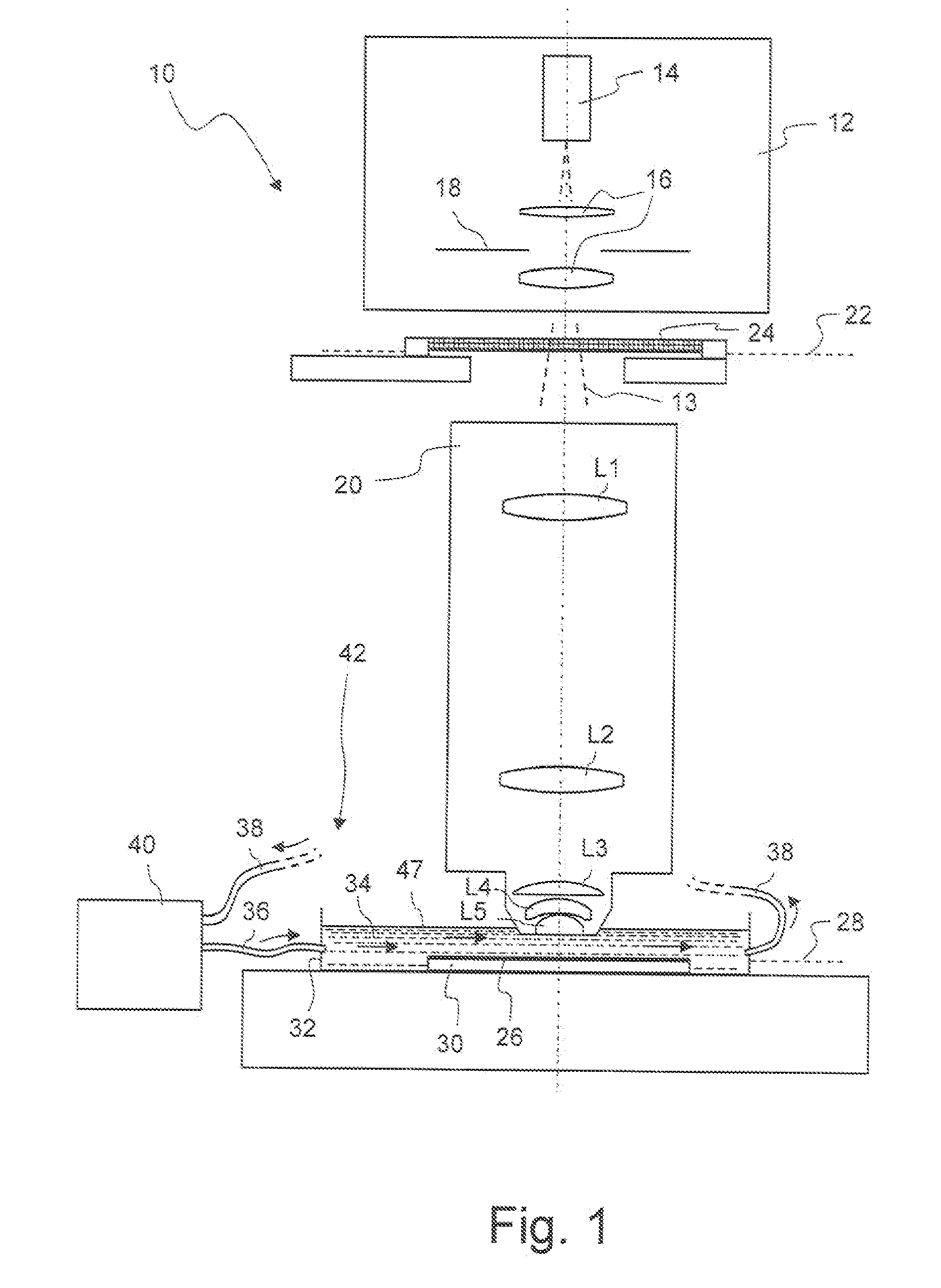
[0069]FIG. 1 shows a meridional section through a microlithographic projection exposure apparatus designated as a whole by 10 in a greatly simplified representation. The projection exposure apparatus 10 includes an illumination system 12 for generating projection light 13, which comprises a light source 14, illumination optics indicated at 16 and an aperture 18. In the embodiment illustrated the projection light 13 has a wavelength λ of 193 nm. The projection exposure apparatus 10 also includes a projection lens 20 containing a multiplicity of lenses, only some of which are indicated as examples in FIG. 1 for reasons of clarity, and which are denoted by L1 to L5. The projection lens 20 serves to image a mask 24 arranged in an object plane 22 of the projection lens 20 on a reduced scale on a photosensitive layer 26. The layer 26, which may consist, for example, of a photoresist, is arranged in an image plane 28 of the projection lens 20 and is applied to a carrier 30.

[0070]The carrie...


PUM

PropertyMeasurementUnit
wavelengthsaaaaaaaaaa
wavelength λaaaaaaaaaa

Abstract

A microlithographic projection exposure apparatus includes a projection lens that is configured for immersion operation. For this purpose an immersion liquid is introduced into an immersion space that is located between a last lens of the projection lens on the image side and a photosensitive layer to be exposed. To reduce fluctuations of refractive index resulting from temperature gradients occurring within the immersion liquid, the projection exposure apparatus includes heat transfer elements that heat or cool partial volumes of the immersion liquid so as to achieve an at least substantially homogenous or at least substantially rotationally symmetric temperature distribution within the immersion liquid.

Description

CROSS-REFERENCE TO RELATED APPLICATIONS[0001]This is a continuation-in-part of International Patent Application PCT / EP2005 / 000246, which was filed on Jan. 13, 2005 and claims benefit of U.S. provisional application Ser. No. 60 / 537,784 filed Jan. 20, 2004. The full disclosure of these earlier applications is incorporated herein by reference.BACKGROUND OF THE INVENTION[0002]1. Field of the Invention[0003]The invention relates to microlithographic projection exposure apparatuses as used for manufacturing highly-integrated electrical circuits and other microstructured components. In particular, the invention relates to projection exposure apparatuses configured for immersion operation. The invention further provides measuring devices for determining the imaging properties of projection lenses.[0004]2. Description of Related Art[0005]Integrated electrical circuits and other microstructured components are usually manufactured by applying a plurality of structured layers to a suitable subs...

Claims


Application Information

Patent Timeline
Patent Type & Authority Applications(United States)
IPC IPC(8): G03B27/42G03B27/52G03F7/20
CPCG03F7/70591G03F7/70691G03F7/7085G03F7/70875G03F7/70891G03F7/70991G03F7/70341G03F7/2041H01L21/0274
Inventor EHRMANN, ALBRECHTWEGMANN, ULRICHHOCH, RAINERMALLMANN, JOERGSCHUSTER, KARL-HEINZLOERING, ULRICHGRUNER, TORALFKNEER, BERNHARDGEUPPERT, BERNHARDSORG, FRANZKUGLER, JENSWABRA, NORBERT
Owner CARL ZEISS SMT GMBH
Why Eureka
Try Eureka