Multi-phase modulator

a multi-phase modulator and phase technology, applied in the field of multi-phase modulators, can solve problems such as limiting the scalability of these approaches

Active Publication Date: 2008-12-18
UNIV OF COLORADO THE REGENTS OF
View PDF8 Cites 115 Cited by
  • Summary
  • Abstract
  • Description
  • Claims
  • Application Information

AI Technical Summary

Problems solved by technology

An N-phase system requires N high-resolution digital pulse-width modulators, which limits the scalability of these approaches.

Method used


Image

  • Multi-phase modulator
  • Multi-phase modulator
  • Multi-phase modulator

Examples


example

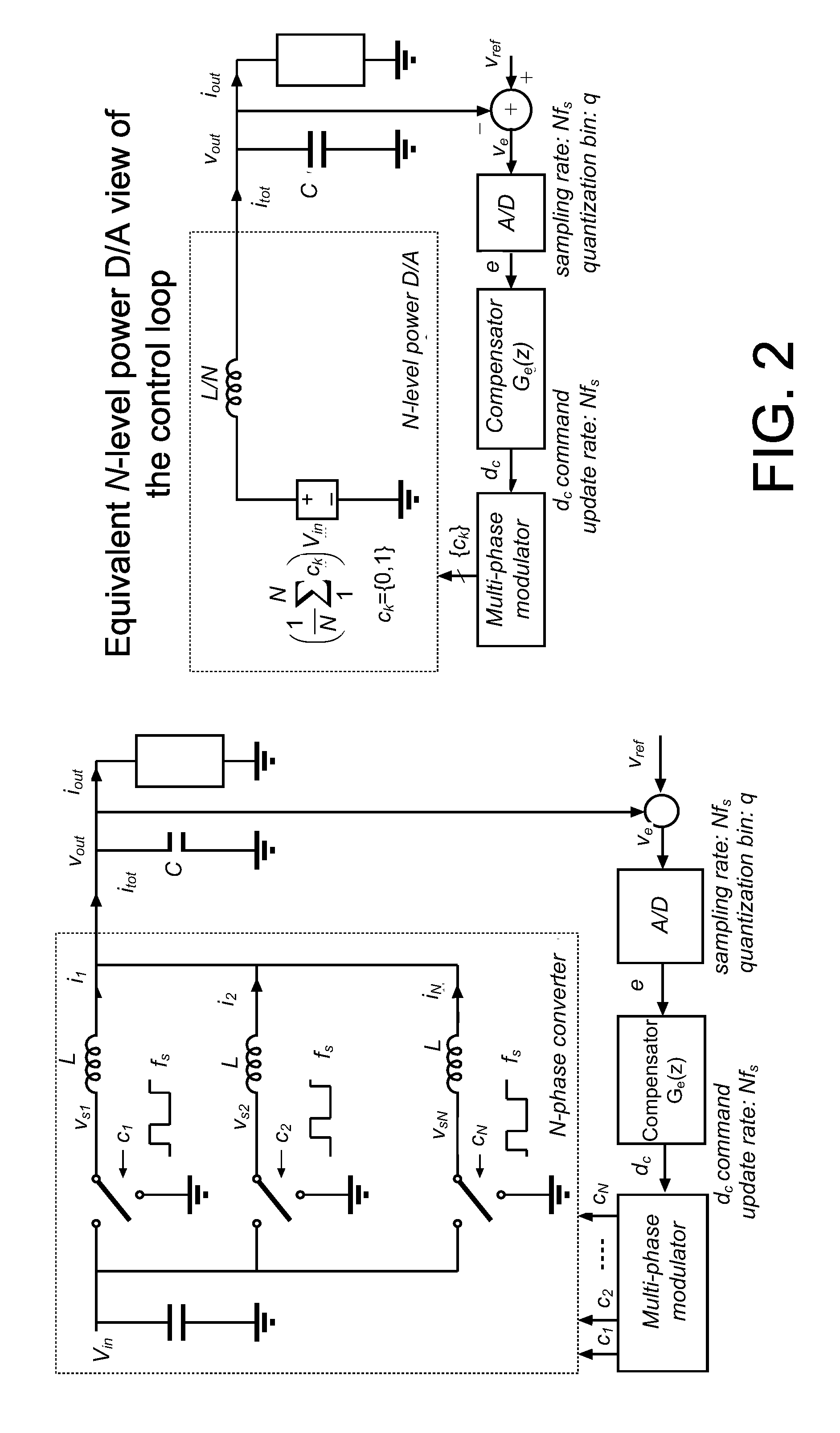
[0040]A custom IC was developed and tested based on the architecture shown in FIG. 2 for a 16 phase output, n=4, N=16. The IC was fabricated in a 0.35μ CMOS process and includes two complete versions of the digital MPM. Both versions include identical copies of the MPM core but with different types of DPWM LSB modules: counter and delay-line based. The area requirements for each of the modules and total MPM designs are shown in Table I.

TABLE ISUMMARY OF PHYSICAL AREA FOR THE TWO MPM VERSIONSAND MODULESModuleAreaCounter-based MPM0.04 mm2MPM Core0.03 mm2Counter LSB0.01 mm2Delay-line based MPM0.23 mm2MPM Core0.03 mm2Delay-line LSB0.20 mm2

[0041]The delay-line based MPM was designed for a clock signal frequency, fclock=N·fs=64 MHz, resulting in a single phase switching frequency fs=4 MHz. The delay-line LSB was designed using a digital delay-locked loop (DLL) to self-tune to the clock input with a 2:1 tuning range, as introduced in V. Yousefzadeh, T. Takayama, D. Maksimović, “Hybrid DPWM...


PUM


Abstract

An architecture is described for digital multi-phase modulators (MPM) that leads to an efficient, high performance hardware realization. The combined modulator, switching phases and output filter can be viewed as a multi-level digital to analog converter with high power output, or a power D / A, and concepts used in D / A converters are leveraged to achieve high performance and hardware efficiency. The modulator can be split into three functional blocks including a decoder that determines how many phases are on at any time, a selector that determines which phases are on at any time, and a single high resolution module that is time shared among all phases. The resulting architecture scales favorably with a large number of phases, fs, facilitates fast update rates of the input command well above the single phase switching frequency and is compatible with a wide range of known DPWM techniques for the LSB module and resolution-enhancement techniques such as dithering or Σ-Δ modulation.

Description

CROSS-REFERENCE TO RELATED APPLICATIONS[0001]This application claims the benefit of U.S. provisional application No. 60 / 944,483 filed 15 Jun. 2007, which is hereby incorporated by reference as though fully set forth herein.BACKGROUND[0002]a. Field[0003]The instant invention relates to a multi-phase modulator for a multi-phase power converter.[0004]b. Background[0005]A high performance multi-phase modulator (MPM) is a component in multi-phase power supplies. A number of previous approaches to realizing digital multi-phase modulators have followed the architecture of standard analog multi-phase pulse-width modulators (PWM) where a separate modulation ramp signal is generated for each phase, and the ramp signals are shifted in time by Ts / N, where fs=1 / Ts is the per-phase switching frequency. An N-phase system requires N high-resolution digital pulse-width modulators, which limits the scalability of these approaches.[0006]A different architecture, requiring a single high-resolution unit...

Claims


Application Information

Patent Timeline
Patent Type & Authority Applications(United States)
IPC IPC(8): H02J1/00
CPCH02M3/1584H03K7/08
Inventor MAKSIMOVIC, DRAGANZANE, REGANCAROSA, ANTHONY
Owner UNIV OF COLORADO THE REGENTS OF
Why Eureka
Try Eureka