Holey fiber and method of manufacturing the same

a technology of holey fiber and manufacturing method, which is applied in the direction of manufacturing tools, cladded optical fiber, instruments, etc., can solve the problems of reducing productivity, disadvantageous shape of air holes, and large number of air holes

Inactive Publication Date: 2008-12-18
FURUKAWA ELECTRIC CO LTD
View PDF8 Cites 32 Cited by
  • Summary
  • Abstract
  • Description
  • Claims
  • Application Information

AI Technical Summary

Benefits of technology

[0010]According to an aspect of the present invention, there is provided a method of manufacturing a holey fiber including a core region and a cladding region surrounding the core region and having air holes arranged around the core region in layers. The method includes forming a preform by arranging a core rod at a center of a jacket tube and arranging capillary tubes having hollows around the core rod inside the jacket tube; and drawing the preform by heat melting the preform in a heating furnace while controlling at least one of a gas pressure to be applied to insides of the hollows of the capillary tubes, a temperature of the heating furnace, and a drawing speed, based on a structure of air holes to be formed in a first layer from the core region.

Problems solved by technology

Shapes of the air holes can disadvantageously deform during the drawing process.
Furthermore, upon arranging the air holes in triangular lattices in such layers, a large number of the air holes are necessary.
This reduces the productivity.

Method used


Image

  • Holey fiber and method of manufacturing the same
  • Holey fiber and method of manufacturing the same
  • Holey fiber and method of manufacturing the same

Examples


first embodiment

[0028]A holey fiber manufacturing method according to the present invention and details of a holey fiber 10 are described below. The holey fiber 10 is manufactured by the stack and draw method.

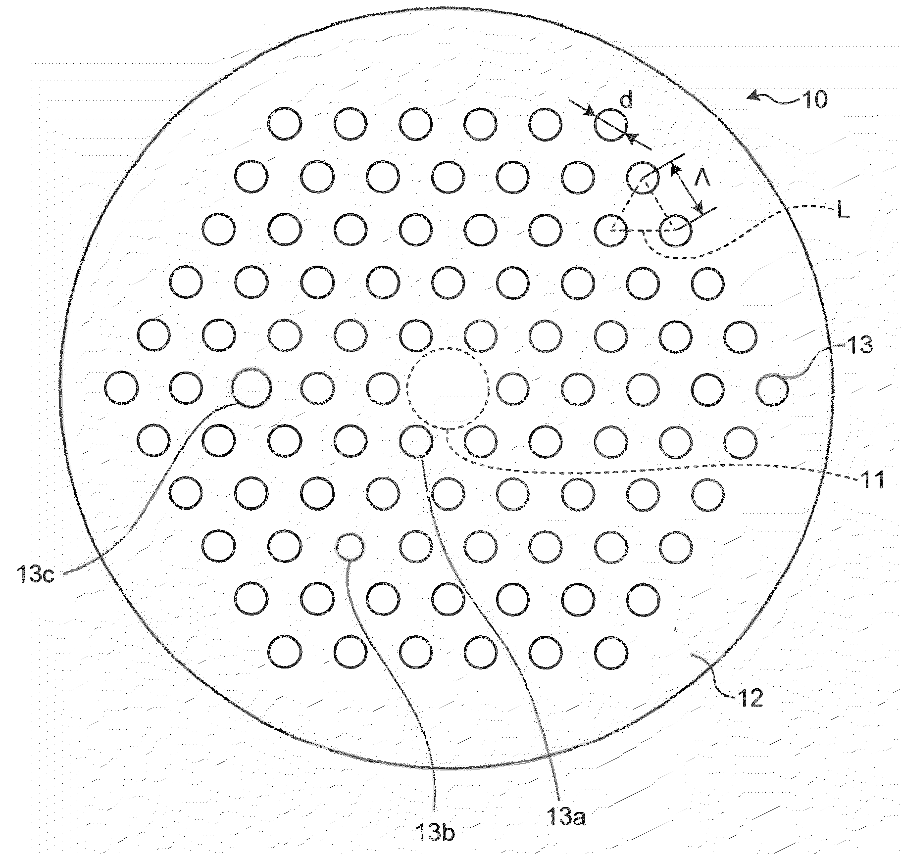
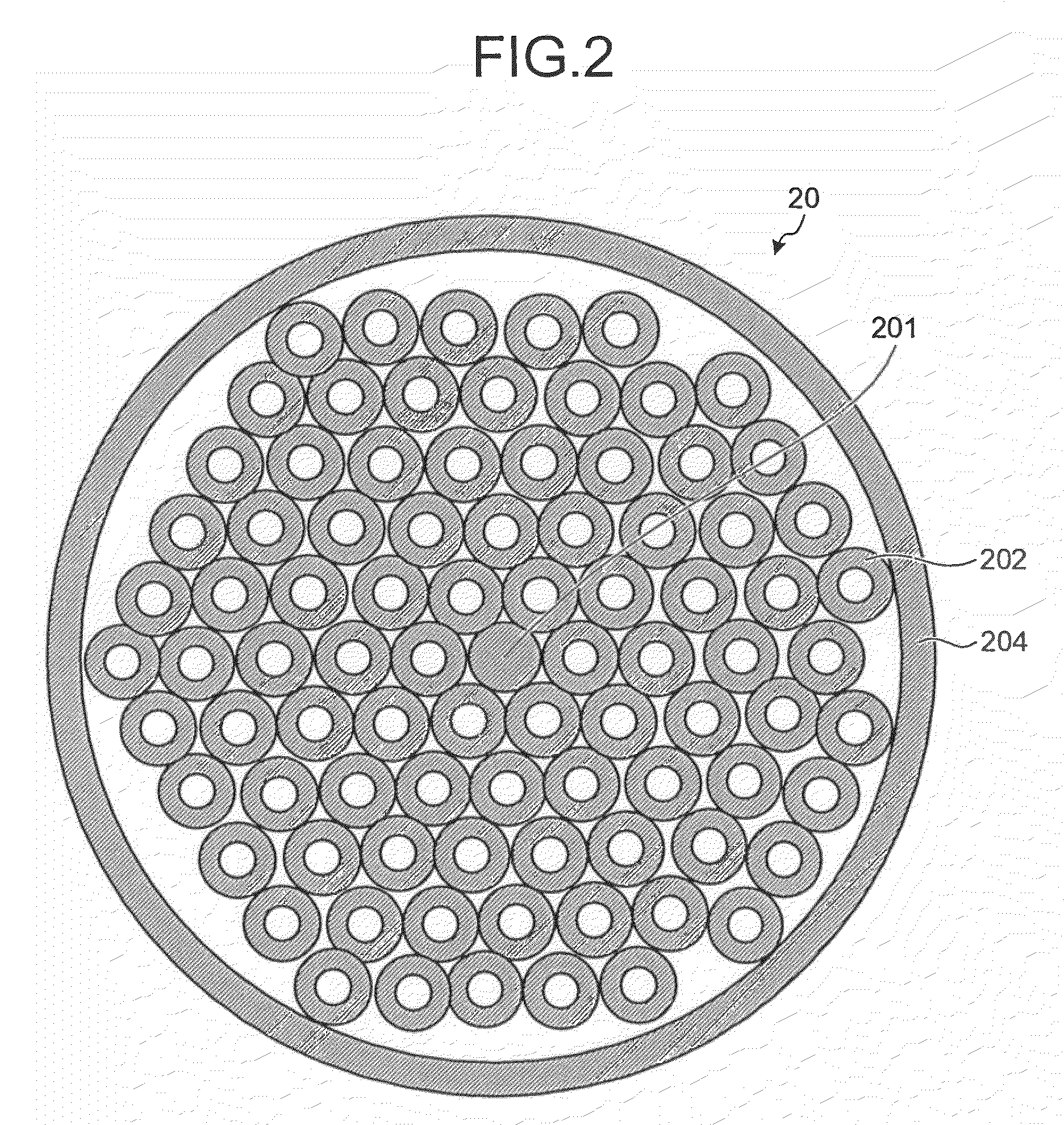
[0029]FIG. 1 is a schematic diagram of the holey fiber 10. The holey fiber 10 includes a core region 11 at a center of the holey fiber 10 and a cladding region 12 surrounding the core region 11. The cladding region 12 contains air holes 13. The core region 11 and the cladding region 12 are made of silica glass and the like.

[0030]The cladding region 12 contains five layers of the air holes 13 in a triangular lattice L. If a diameter of the air holes 13 is represented by “d” and a lattice constant of the triangular lattice L, that is, a pitch between centers of the air holes 13, is represented by “Λ”, the characteristics of the holey fiber can be controlled by adjusting values of Λ and d / Λ as appropriate.

[0031]Inner diameters and positions of the air holes 13 can vary because of variations in a ...

second embodiment

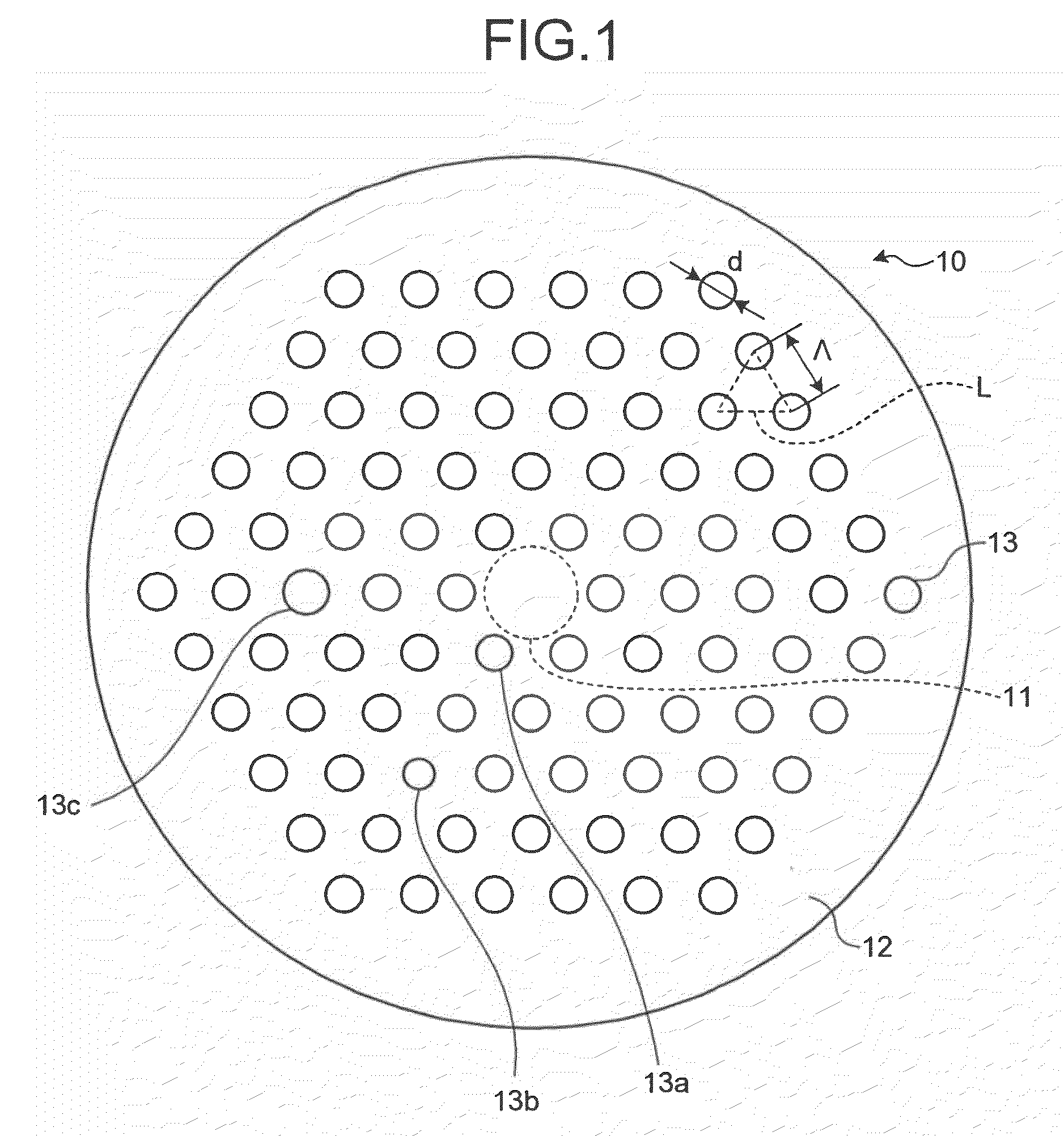
[0043]FIG. 4 is a schematic diagram of a preform 30 used in the method according to the The preform 30 is formed in the manner explained below. A core rod 301 and capillary tubes 302 and 303 manufactured by a pull method and a draw method are prepared. At this process, inner diameters and outer diameters of the capillary tubes 302 and 303 can vary because of variations in a manufacturing process. Therefore, errors of the inner diameters of the capillary tubes 302 and 303 from an inner-diameter reference value and errors of the outer diameters of the capillary tubes 302 and 303 from an outer-diameter reference value are measured, and the capillary tubes 302 of which errors are smaller than those of the capillary tubes 303 are selected. Specifically, the capillary tubes 302 of which errors are smaller than the average of the errors of all the capillary tubes are selected.

[0044]More preferably, assuming that the number of the capillary tubes to be arranged on the first layer is “n”, t...


PUM

PropertyMeasurementUnit
wavelengthaaaaaaaaaa
bending diameteraaaaaaaaaa
inner diameteraaaaaaaaaa

Abstract

A method of manufacturing a holey fiber includes forming a preform and drawing the preform. The forming includes arranging a core rod at a center of a jacket tube and arranging capillary tubes having hollows around the core rod inside the jacket tube. The drawing includes heat melting the preform in a heating furnace while controlling at least one of a gas pressure to be applied to insides of the hollows of the capillary tubes, a temperature of the heating furnace, and a drawing speed, based on a structure of air holes to be formed in a first layer from the core region.

Description

BACKGROUND OF THE INVENTION[0001]1. Field of the Invention[0002]The present invention relates to a holey fiber and a method of manufacturing the same.[0003]2. Description of the Related Art[0004]A holey fiber is an optical fiber having air holes arranged in a periodic manner in a cladding region. The cladding region surrounds a core region. The cladding region has reduced average refractive index because of the presence of the air holes so that a light passes almost entirely through the core region because of the total reflection of the light.[0005]Because the refractive index of holey fibers can be controlled by controlling various parameters of the air holes, the holey fibers can realize unique properties that can not be realized in the other optical fibers such as endlessly single mode (ESM) and anomalous dispersion at a short wavelength. The ESM means that a cut-off wavelength is not present and a light is transmitted in a single mode at all wavelengths. With the ESM, it is poss...

Claims


Application Information

Patent Timeline
Patent Type & Authority Applications(United States)
IPC IPC(8): G02B6/032B29D11/00
CPCB29D11/00663G02B6/02019G02B6/02333G02B6/29377C03B37/0122C03B37/02781C03B2203/14C03B2203/42C03B2205/10Y02P40/57
Inventor MUKASA, KAZUNORI
Owner FURUKAWA ELECTRIC CO LTD
Why Eureka
Try Eureka