Valve Mounting Arrangement For a Refrigeration Compressor

a technology for refrigeration compressors and mounting arrangements, which is applied in the direction of positive displacement liquid engines, liquid fuel engines, lighting and heating apparatus, etc., can solve the problems of high construction cost and construction that requires additional machining operations of the faces of blank valve plates, and achieves simple and reliable manners.

Inactive Publication Date: 2008-12-18
WHIRPOOL SA
View PDF32 Cites 41 Cited by
  • Summary
  • Abstract
  • Description
  • Claims
  • Application Information

AI Technical Summary

Benefits of technology

[0011]Thus, it is an object of the present invention to provide a valve mounting arrangement for a refrigeration compressor, which allows providing and maintaining, in a simple and reliable manner, the positioning of a valve element on the valve plate.
[0012]Another object of the present invention is to provide an arrangement as cited above, which reduces the process steps of mounting the valve element on the valve plate.
[0013]An additional object is to provide an arrangement as cited above, which has a reduced cost.SUMMARY OF THE INVENTION

Problems solved by technology

In spite of this advantage, said construction presents a high cost due to the raw material that is consumed in the production of said suction valve.
Furthermore, such construction requires additional machining operations of the faces of the blank valve plate.
Nevertheless, although not presenting the constructive deficiencies of the single-piece suction valve, said solution has the disadvantage of requiring an additional process for mounting the valve plate assembly, which is required to guarantee the correct positioning of the valve element in the recess.

Method used


Image

  • Valve Mounting Arrangement For a Refrigeration Compressor
  • Valve Mounting Arrangement For a Refrigeration Compressor
  • Valve Mounting Arrangement For a Refrigeration Compressor

Examples


Embodiment Construction

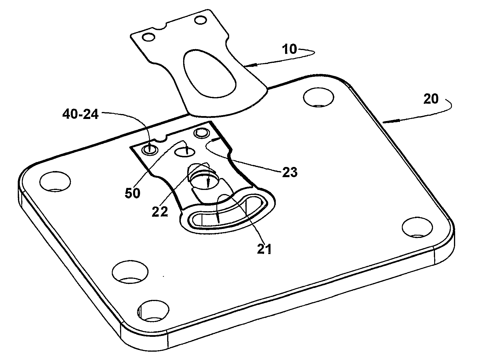
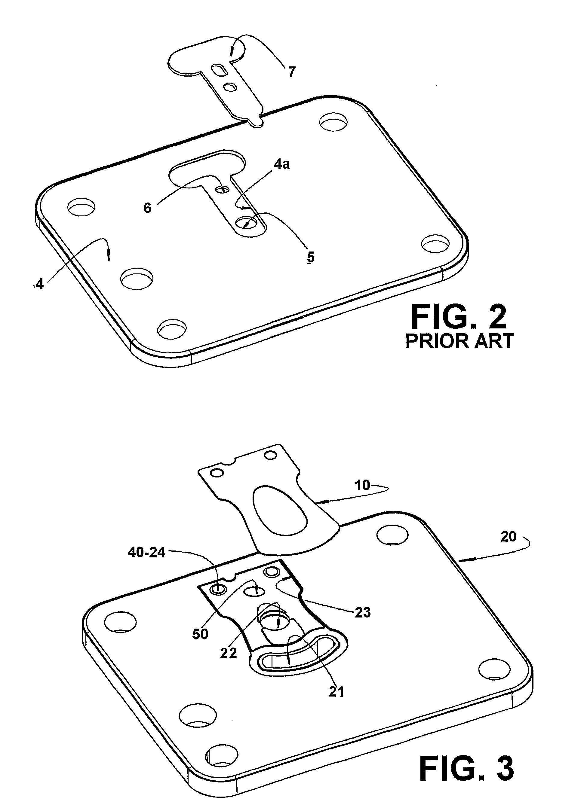
[0022]The present invention will be described in relation to a refrigeration compressor comprising, in the interior of a casing (not illustrated), a motor-compressor assembly including a cylinder 1 that lodges a piston 2 reciprocating within a compression chamber 3 defined in the interior of said cylinder 1 between a top portion of said piston 2 and a valve plate 4 seated onto an end portion of the cylinder 1, said prior art valve plate 4 being described below.

[0023]The compressor further carries an electric motor (not illustrated) that drives said piston 2 in suction and compression strokes of a refrigerant gas of a refrigeration system to which the compressor is coupled, said refrigerant gas being admitted in the interior of the compression chamber 3, from a suction line of the refrigeration system to which the compressor is coupled.

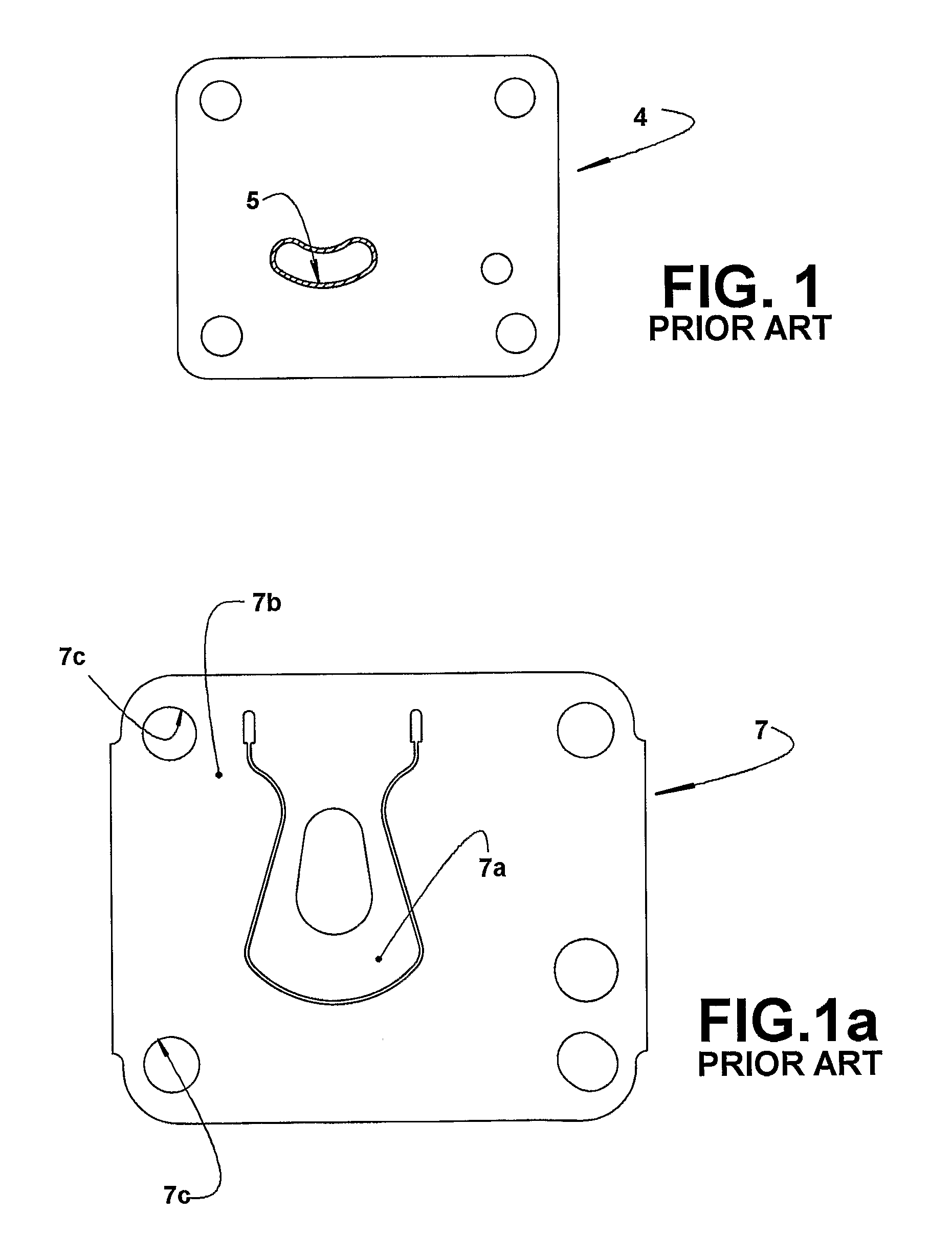
[0024]The prior art valve plate 4 illustrated in FIGS. 1, 1a and 2 is provided with at least one suction orifice 5 and with at least one discharge ori...


PUM


Abstract

A valve mounting arrangement for a refrigeration compressor which presents a compression chamber closed by a valve plate having a suction orifice closed by a valve element having a mounting end portion. The mounting arrangement comprises: a first retaining means to retain the mounting end portion of the valve element inside a receiving recess of the valve plate; and at least one orientation projection carried by receiving recess and / or the mounting end portion of the valve element and to be fitted into an orientation recess in the other part; and / or a second retaining means provided between the receiving recess and the mounting end portion of the valve element, so as to avoid the latter from moving from the receiving recess before mounting the first retaining means.

Description

FIELD OF THE INVENTION[0001]The present invention refers to an arrangement for mounting a valve, which is not of the single piece type, in a refrigeration compressor, such as that used in small refrigeration systems.BACKGROUND OF THE INVENTION[0002]The energetic efficiency of the refrigeration compressors is mostly attributed to the good performance of their valves in the control of the gas flow.[0003]In the reciprocating refrigeration compressors, the compression of the refrigerant gas is achieved by movement of the piston, which is driven by a driving means, such as a mechanism of the connecting rod-crankshaft type, or by a linear motor. The piston reciprocates inside the compression chamber and, at the moment it begins to return from the upper dead point to the lower dead point, in its suction stroke, it draws the refrigerant gas from the suction line of the refrigeration system to which the compressor is coupled (that is, coming from the evaporator of the refrigeration system). ...

Claims


Application Information

Patent Timeline
Patent Type & Authority Applications(United States)
IPC IPC(8): F04B39/10
CPCF04B39/1066F04B39/1073F04B39/02F25B31/00F16N15/00F04B2205/14F16N2200/12Y10S403/08F04B39/12F25B41/20
Inventor RAMSDORF, ROBERTOKRUEGER, GUILHERME ALAN
Owner WHIRPOOL SA
Why Eureka
Try Eureka