Screw-Type Solid Bowl Centrifuge

a centrifuge and solid-bowl technology, which is applied in the direction of centrifuges, rotary centrifuges, separation devices, etc., can solve the problems of inability to achieve sufficient high efficiency in the extraction of olive oil, for example, and achieve the effect of improving the dewatering and/or deoiling, and surprisingly increasing the efficiency of various centrifugal separation processes in three-phase separation

Inactive Publication Date: 2008-12-18
GEA MECHANICAL EQUIP
View PDF5 Cites 6 Cited by
  • Summary
  • Abstract
  • Description
  • Claims
  • Application Information

AI Technical Summary

Benefits of technology

[0013]The solid phase can be set, for example, at a residual moisture content of approximately 40% to 55%. It is thereby possible to meet the essential requirements as to a residual moisture content, even as a function of the respective provisions to be adhered to.
[0014]By the screw or centrifuge, according to the present disclosure, the two-phase oil extraction, and also the three-phase oil extraction still occasionally used, can be improved. In the latter case, the oil is separated as a liquid phase in a three-phase separating cut from a second phase, essentially from water, and from a third phase, essentially from solids.
[0015]According to the present disclosure, by a combination of clearances and of “intermediate blade segments” in the conveying path on only two screw flights, the efficiency of various centrifugal separating processes in three-phase separation can surprisingly be markedly increased further, as compared with the prior art. That is because an acceleration of the solid, both in the circumferential direction and in the axial direction, is achieved. This entails be ter phase separation of the viscoelastic and compressible paste. This prevents the situation where the inflowing paste, immediately after flowing in, is compacted when it impinges onto the solid in the rotor.
[0016]In accordance with the present disclosure, the screw can also be retrofitted easily in existing centrifuges.
[0017]The screw, according to the present disclosure, is suitable for use in a method for oil extraction from fruits and seeds and for the better dewatering and / or deoiling of mashes including organic materials, for example seed mashes, pod mash, animal tissue, such as fish, protein, and fatty tissue cells. Moreover, the situation is prevented where the inflowing paste, immediately after flowing in, is compacted when it impinges onto the solid in the rotor.

Problems solved by technology

These blade segments, however, sometimes extend well into the conical portion, this being a disadvantage.
Furthermore, they are distributed on the circumference of the screw body in the entire region of the latter, and this has likewise proved to be somewhat of a disadvantage.
By the two references just mentioned above, a sufficiently high efficiency in the extraction of olive oil, for example, cannot be achieved.

Method used


Image

  • Screw-Type Solid Bowl Centrifuge
  • Screw-Type Solid Bowl Centrifuge
  • Screw-Type Solid Bowl Centrifuge

Examples


Embodiment Construction

[0026]Terms, such as top or bottom refer to a viewing of FIGS. 1 and 2 and are to be understood as being by way of example.

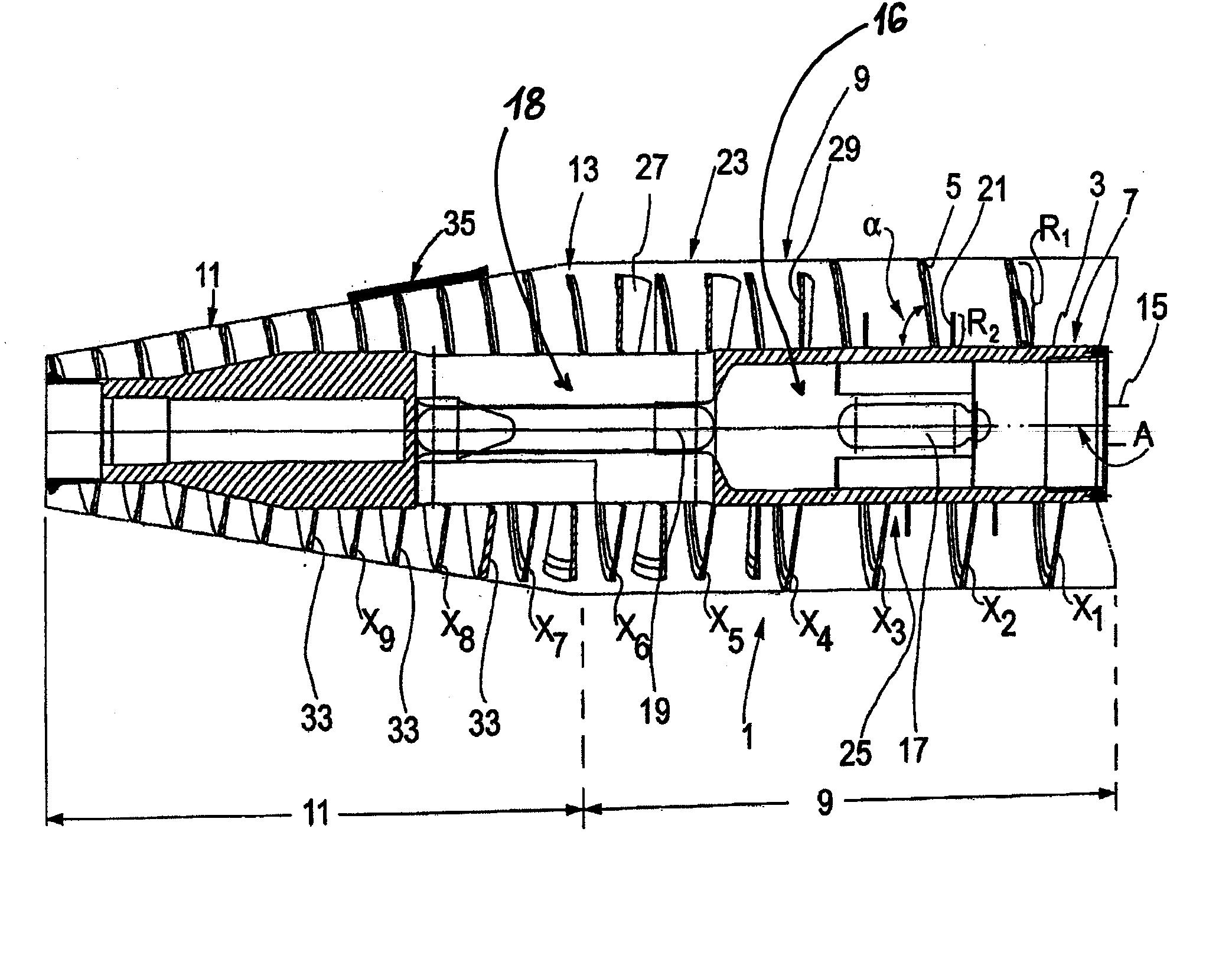
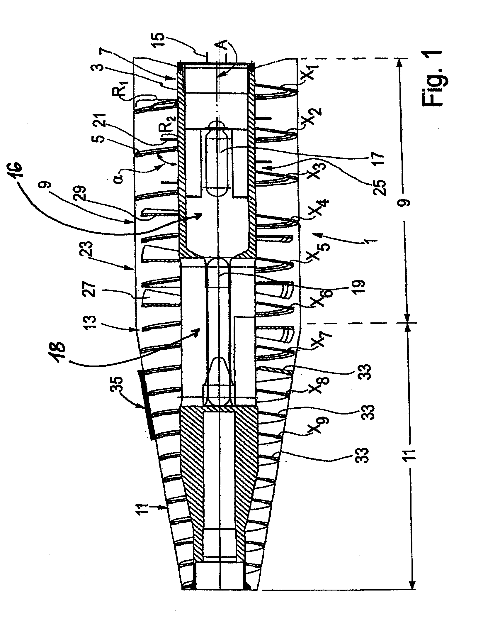
[0027]FIG. 1 shows a screw 1 for a screw-type solid-bowl centrifuge, or it may be referred to as a decanter screw. Screw 1 includes a screw body 3 and a main screw blade 5 which surrounds the screw body 3 and which forms a plurality of screw flights X1, X2, X3, . . . Xn. The main screw blade 5 is inclined at an acute angle α to the surface of the screw body 3 in the direction of a tapering end or portion 11 of the screw 1. That is, in a conveying direction for the solid to be discharged. Angle α is relative to screw axis A or to the screw body 3 in a conical or tapering region, which angle α is smaller than 90°. A pitch of the screw 1 or helix is designated by P.

[0028]A “screw flight” is designated as a screw turn, for example, 3600, of a single-flight screw. According to the present disclosure, screw flights are counted from a liquid discharge area and are desi...


PUM


Abstract

A screw-type solid-bowl centrifuge including a rotatable drum having a tapering portion and a cylindrical portion. The rotatable screw includes a screw body, at least one main screw blade surrounding the screw body and forming a plurality of screw flights. The plurality of screw flights forms a conveying path configured to transport a material to be processed in the centrifuge. Two blade segments are arranged in the conveying path in portions of the plurality of screw flights. The at least one main screw blade is provided in a region of the blade segments that includes clearances configured to allow a throughflow of the material to be processed to flow between adjacent screw flights.

Description

BACKGROUND AND SUMMARY[0001]The present disclosure relates to a screw-type solid-bowl centrifuge including a rotatable drum having a tapering portion and a cylindrical portion. The rotatable screw includes a screw body, at least one main screw blade surrounding the screw body and forming a plurality of screw flights. The plurality of screw flights forms a conveying path configured to transport a material to be processed in the centrifuge. Two blade segments are arranged in the conveying path in portions of the plurality of screw flights. The at least one main screw blade is provided in a region of the blade segments that includes clearances configured to allow a throughflow of the material to be processed to flow between adjacent screw flights.[0002]Decanter screws are known from the prior art, in which clearances are provided in the screw blade, as, for example, from DE 41 32 693 A1. Moreover, it is also known to form screw flights resembling blade segments, as, for example, from W...

Claims


Application Information

Patent Timeline
Patent Type & Authority Applications(United States)
IPC IPC(8): B04B1/20
CPCB04B1/20B04B2001/2033B04B2001/2041B04B2001/205Y10S494/901
Inventor HRUSCHKA, STEFFENHULSMANN, ROGER
Owner GEA MECHANICAL EQUIP
Why Eureka
Try Eureka