Controller and control system for internal combustion engine

a control system and internal combustion engine technology, applied in the direction of electrical control, process and machine control, instruments, etc., can solve the problems of catalyst device deterioration, catalyst device temperature rise, operation likely to fall into the state, etc., to prevent air-fuel ratio, reduce the frequency of positive determination, and reduce the upper limit

Inactive Publication Date: 2008-12-18
DENSO CORP
View PDF9 Cites 10 Cited by
  • Summary
  • Abstract
  • Description
  • Claims
  • Application Information

AI Technical Summary

Benefits of technology

[0008]The present invention has been established in order to solve the aforementioned problems and an object of the present invention is to provide an internal combustion engine controller and an internal combustion engine control system that can suppress such a drawback in which an air-fuel ratio deviates from an optimum value toward the side of a lean air-fuel ratio when an alternate fuel is blended with a regular fuel.
[0010]When it is positively determined that the requested injection time is larger than the injectable time) the fuel pump is subjected to load-up operation so that the fuel feed pressure may increase. Consequently, the quantity of a fuel injected from the fuel injector per unit time increases and hence the quantity of a fuel injected during the injectable time also increases even when the injectable time is not changed. As a result, it is possible to reduce the frequency of the undesirable cases where a fuel of a quantity that gives an optimum air-fuel ratio conforming to a requested intake air flow rate responding to an accelerator stroke can no more be injected as the quantity of an alternate fuel blended with a regular fuel increases. Further it is possible to suppress the drawback in which the air-fuel ratio deviates from the optimum value toward the side of a lean air-fuel ratio.
[0015]When it is positively determined that the requested injection time is greater than the injectable time, the upper limit is subtractively corrected so as to be smaller. Consequently, the frequency of the cases where an engine speed comes to such a high rotation speed as exceeding the upper limit can be decreased. Hence the frequency of the cases where the injectable time is shorter than the requested injection time is also decreased, and the frequency of positive determination can be suppressed. As a result, it is possible to prevent an air-fuel ratio from deviating from the optimum value toward the side of a lean air-fuel ratio even in the undesirable cases where a fuel of a quantity that gives an optimum air-fuel ratio conforming to a requested intake air flow rate responding to an accelerator stroke can not be injected.

Problems solved by technology

When an alternate fuel is fed into a fuel tank in the state where a regular fuel remains therein to produce a composite fuel, the composite fuel is injected from the fuel injector and on this occasion the following problems arise.
In the operational region of a high output shaft rotation speed of an internal combustion engine in particular, the time required for one combustion cycle shortens, thus the injectable time also shortens, and resultantly the operation is likely to fall into the state where the requested injection time exceeds the injectable time.
In the case where the internal combustion engine is a gasoline engine in particular, if lean combustion occurs due to a lean air-fuel ratio, the combustion state is destabilized, thereby the amounts of HC and O2 flowing into a catalyst device increase, the HC and O2 are combusted in the catalyst device, and resultantly the temperature of the catalyst device rises and the catalyst device deteriorates.

Method used


Image

  • Controller and control system for internal combustion engine
  • Controller and control system for internal combustion engine
  • Controller and control system for internal combustion engine

Examples


first embodiment

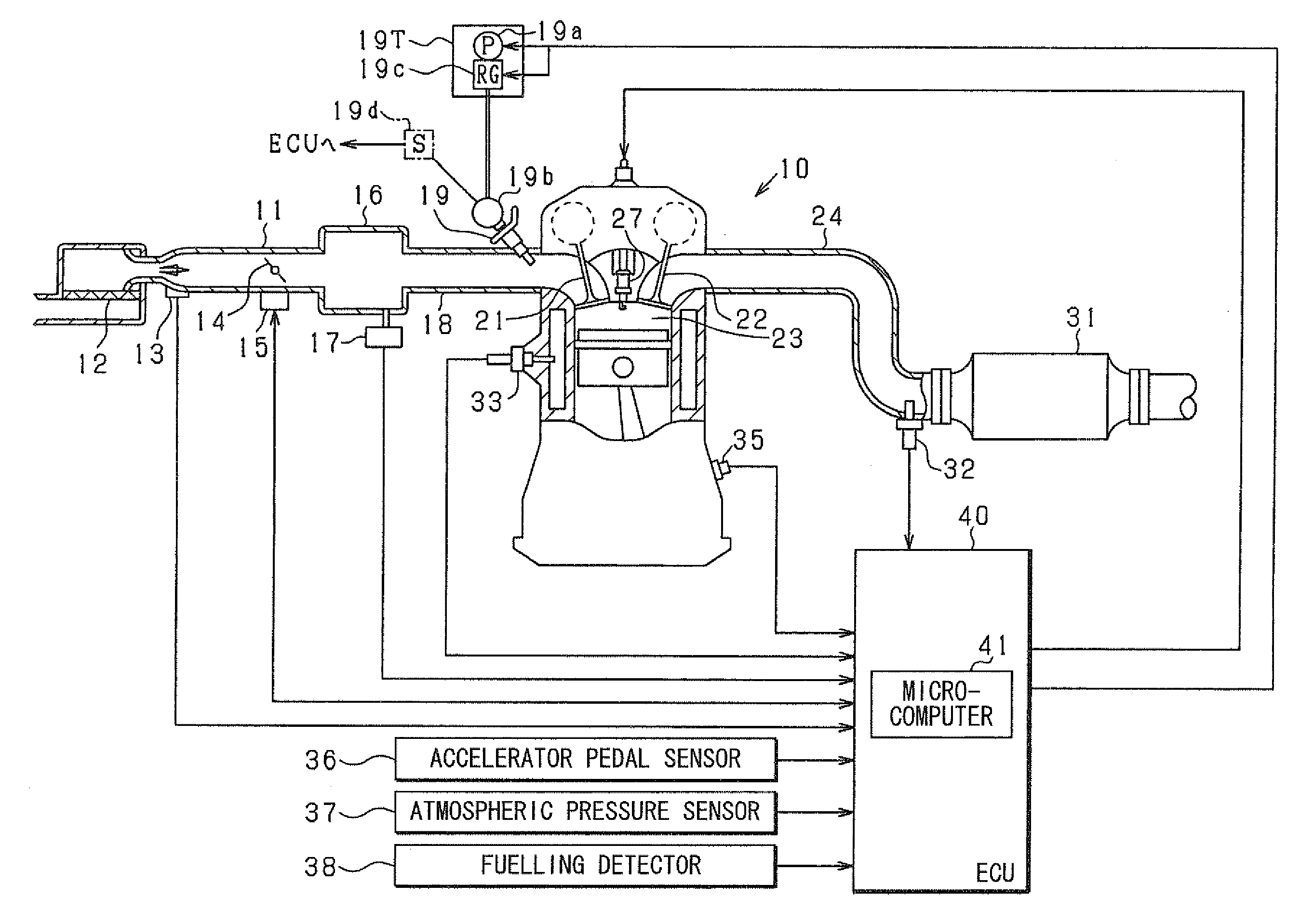
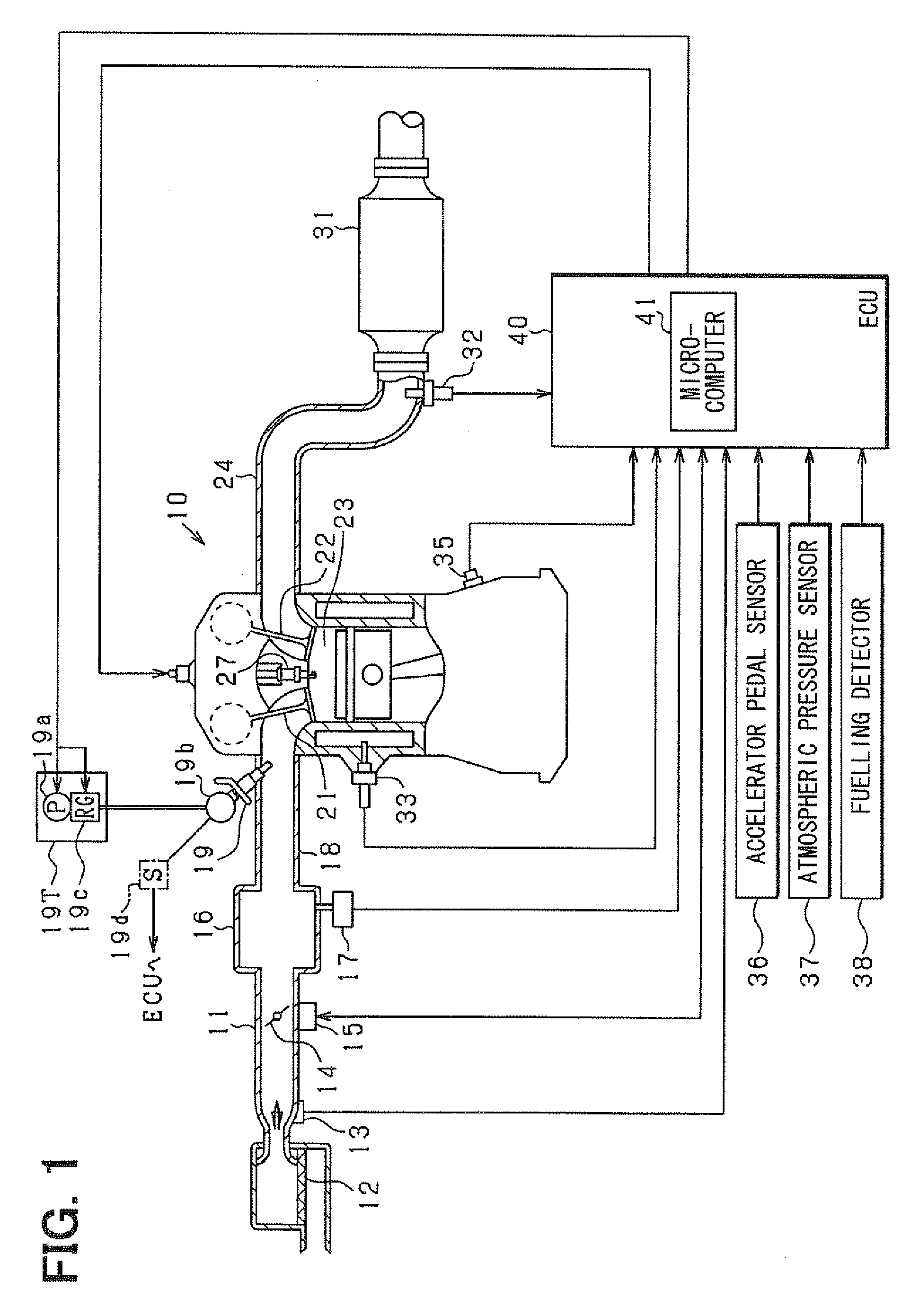
[0031]In the present embodiment, an internal combustion engine control system is configured with a vehicle-mounted multiple cylinder gasoline engine and, in the control system, the control of a fuel injection quantity and the control of ignition timing are carried out mainly with an electronic control unit (hereunder referred to as an ECU) functioning as an internal combustion engine controller. Firstly, a general configuration diagram of an internal combustion engine control system is explained in reference to FIG. 1.

[0032]In an engine 10 shown in FIG. 1, an air cleaner 12 is disposed on the uppermost stream side of an intake pipe 11 and an air flow meter 13 to detect an intake air flow rate is disposed on the downstream side of the air cleaner 12. On the downstream side of the air flow meter 13, a throttle valve 14 (an intake air flow rate control valve) the degree of opening of which is adjusted with a throttle actuator 15 comprising a DC motor or the like is disposed. The openin...

second embodiment

[0074]Whereas load-up operation is executed by increasing the drive duty ratio of the fuel pump 19a in the aforementioned first embodiment, in the present embodiment a configuration for feedback control is adopted so that the fuel pressure in the delivery pipe 19b (feed pressure) may take a target pressure (a target fuel pressure) and the load-up operation is executed by increasing the target fuel pressure.

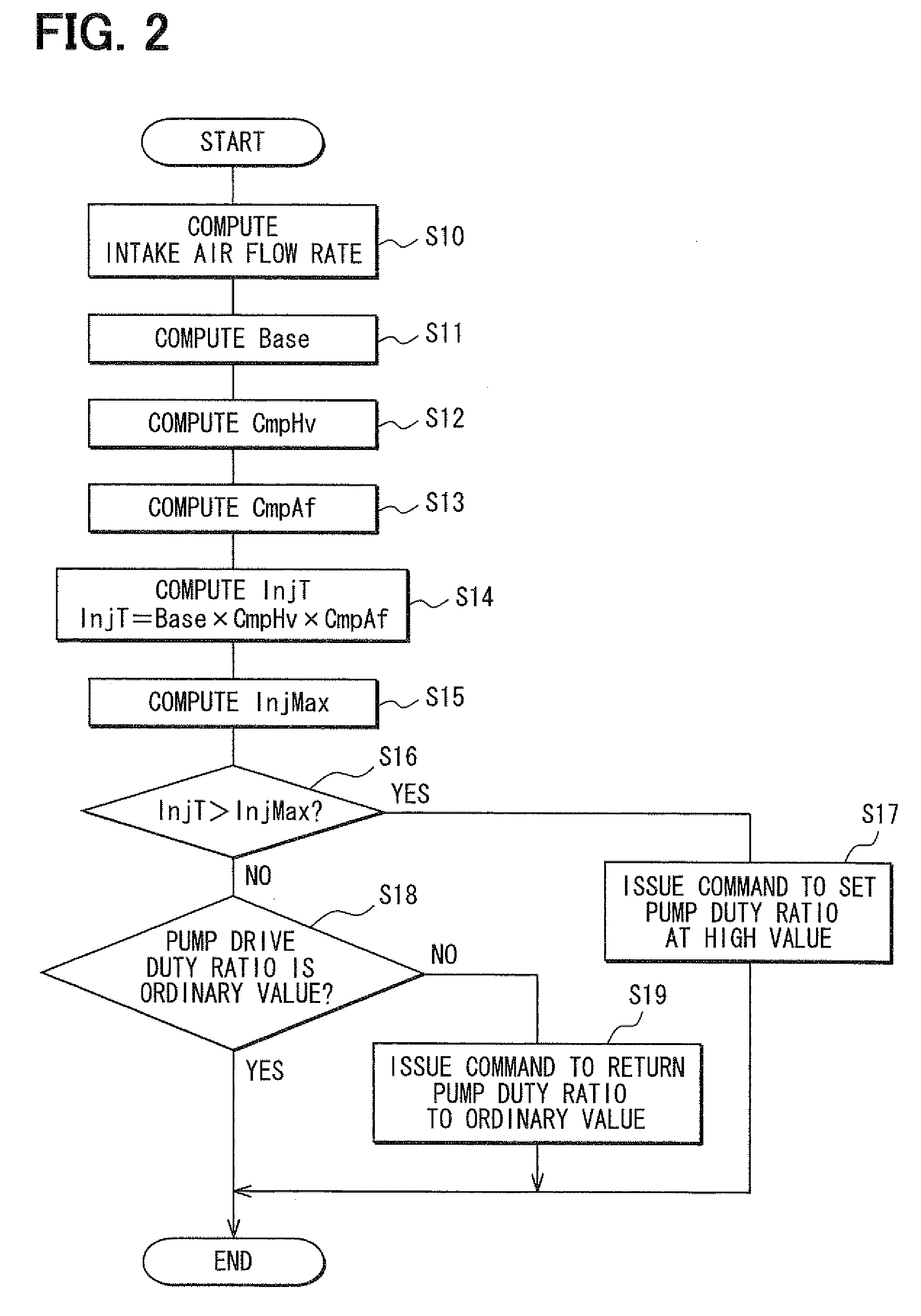
[0075]FIGS. 6 and 7 are flowcharts showing the control procedure of the fuel pump 19a according to the present embodiment and the same codes are named to the steps of the same processes as shown in FIGS. 2 and 3 and the same explanations are used. Further, in the present embodiment, a fuel pressure sensor 19d to detect the fuel pressure in the delivery pipe 19b (refer to the dashed-dotted line in FIG. 1) is disposed. The other parts of the configuration are the same as the first embodiment. The signals detected with the fuel pressure sensor 19d are input into the ECU 40.

[0076]Then...

third embodiment

[0092]In the present embodiment, a device that can change a threshold value functioning as a relief pressure is employed as the pressure regulator 19c (a relief valve) shown in FIG. 1 and it is possible to set the threshold value. Then a means for raising the threshold value is employed in place of a means for raising the target fuel pressure P in the event of the aforementioned load-up operation. Also by this means, it is possible to obtain effects similar to those in the above embodiments. Further, it is possible to estimate a load-up quantity on the basis of the raised threshold value and the time and compute a mixing ratio on the basis of the estimated load-up quantity.

[0093]Further, as a modified example of the above configuration, it is also possible to: employ a pressure regulator 19c wherein a threshold value functioning as a relief pressure is fixed; and alternately use two pressure regulators 11c having threshold values different from each other. On this occasion, the pres...


PUM


Abstract

A requested injection time InjT that is necessary for a fuel injector to inject a fuel per one combustion cycle is computed in response to variables of an accelerator manipulated by a driver. An injectable time InjMax per one combustion cycle is computed on the basis of an engine speed, and whether the requested injection time InjT is larger than the injectable time InjMax is determined. Then, when it is positively determined that the requested injection time InjT is larger than the injectable time InjMax, the fuel pump is subjected to load-up operation so as to increase a fuel feed pressure.

Description

CROSS-REFERENCE TO RELATED APPLICATION[0001]This application is based on Japanese Patent Applications No. 2007-156569 filed on Jun. 13, 2007 and No. 2007-156570 filed on Jun. 13, 2007, the disclosures of which are incorporated herein by reference.FIELD OF THE INVENTION[0002]The present invention relates to an internal combustion engine controller and an internal combustion engine control system to control the operational state of an internal combustion engine.BACKGROUND OF THE INVENTION[0003]As shown in JP-2006-183500A, a requested injection time that is necessary for a fuel injector to inject a fuel per one combustion cycle in an internal combustion engine is computed in response to the variables of an accelerator manipulated by a driver. The fuel injector is operated so as to keep the requested injection time and thereby a fuel of a quantity corresponding to an accelerator stroke is injected. In a spark ignition type internal combustion engine such as a gasoline engine for example...

Claims


Application Information

Patent Timeline
Patent Type & Authority Applications(United States)
IPC IPC(8): F02D45/00
CPCF02D19/0605F02D41/0025F02D41/34F02D41/406F02D2200/0612Y02T10/36Y02T10/44F02D19/061F02D19/0628F02D19/084F02D19/088Y02T10/30Y02T10/40
Inventor HIRATA, YASUO
Owner DENSO CORP
Why Eureka
Try Eureka