Automatic Gain Control Apparatus and Method in Wireless Telecommunication System

a wireless telecommunications and gain control technology, applied in gain control, digital transmission, baseband system details, etc., can solve the problem of uniform strength of input signals, and achieve the effect of optimal automatic gain control

Inactive Publication Date: 2008-12-25
POS DATA CO LTD
View PDF9 Cites 4 Cited by
  • Summary
  • Abstract
  • Description
  • Claims
  • Application Information

AI Technical Summary

Benefits of technology

[0013]The present invention is advantageous to resolve a problem related with a measurement period which may occur in a time-division system, thereby having an optimal automatic gain control is performed when, in a wireless telecommunication system, in particular, a portable internet system, automatic gain control is performed.
[0014]Furthermore, the present invention measures the strength of input signals for a period corresponding to an preamble symbol even at the beginning of operation of a Portable Subscriber Station (PSS) before frame synchronization has been accomplished, applies the strength of input signals to the calculation of a gain control value, thereby having an advantage in that optimal automatic gain control is performed regardless of whether frame synchronization has been accomplished.
[0015]Furthermore, according to the present invention, the gain control value is easily acquired by determining the input address of the ROM according to the strength of the input signal (sample power average value) and using the output of the ROM as a gain control value, wherein the ROM has stored the gain control value data which are measured and calculated as a ROM table in advance, the gain control value data corresponding to the strength of input signals.

Problems solved by technology

Generally, in a wireless telecommunication system, there is a characteristic that the strength of input signals is not uniformly maintained and varies within a specified range because of the variation in distance between a Radio Access Station (RAS) and a Portable Subscriber Station (PSS), an interference caused by obstacles, the movement of a PSS, and the variation in environment of a PSS.
Especially, when synchronization has not been accomplished at the beginning of operation of the PSS, the variation of the strength of input signal may cause serious problems.

Method used


Image

  • Automatic Gain Control Apparatus and Method in Wireless Telecommunication System
  • Automatic Gain Control Apparatus and Method in Wireless Telecommunication System
  • Automatic Gain Control Apparatus and Method in Wireless Telecommunication System

Examples


Embodiment Construction

[0021]Hereinafter, an exemplary embodiment of the present invention will be described in detail with reference to the accompanying drawings. Well known functions and constructions are not described in detail since they would obscure the invention in unnecessary detail.

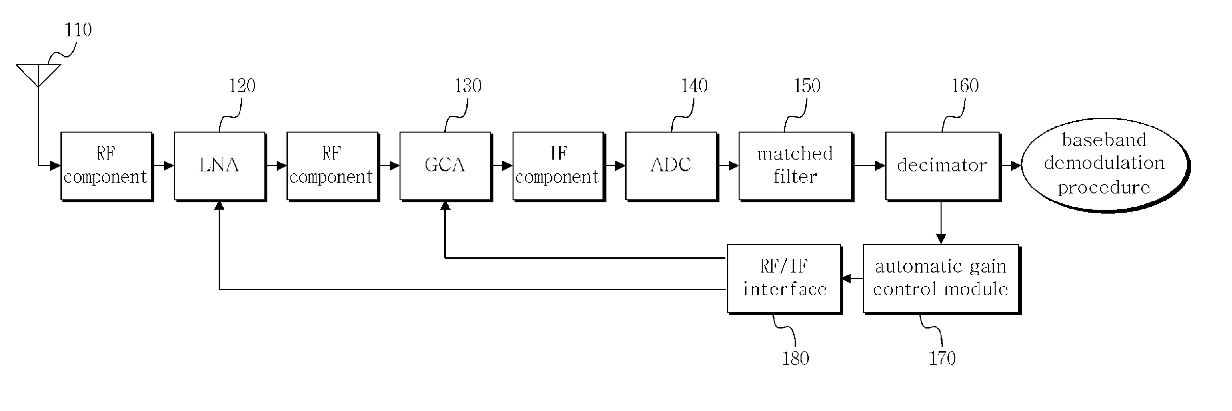
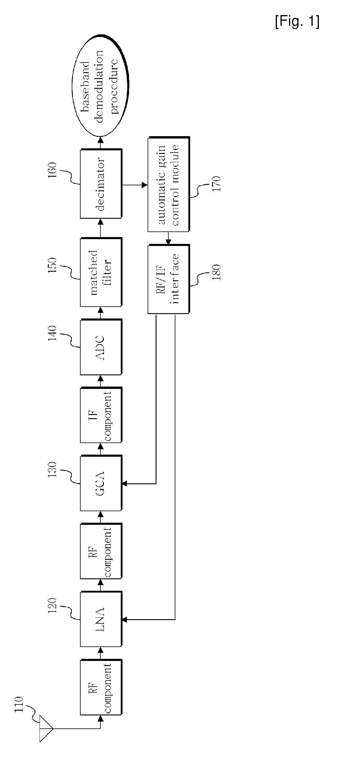
[0022]The construction of the automatic gain control apparatus of a wireless telecommunication system associated with the present invention is schematically described below with reference to FIG. 1.

[0023]Signals which are received through an antenna 110 pass through RF components, and transmitted to a Low Noise Amplifier (LNA) 120. The LNA 120 is an amplifier for minimizing noise that is generated in a Portable Subscriber Station (PSS), while it is the first amplifier located on a reception path.

[0024]The signals, amplified by the LNA 120, pass through the RF components and are then inputted to a Gain Control Amplifier (GCA) 130, which is an amplifier for performing a gain control function by amplifying the input signa...


PUM


Abstract

The present invention relates to an automatic gain control apparatus and method in a wireless telecommunication system which measures the strength of received signals using preamble symbols and automatically control the gain of an amplifier based on the measurement results. The automatic gain control apparatus and method according to present invention performs automatic gain control of measuring sample power in a sample unit for input signals, acquiring a sample power average value during a unit symbol period, detecting a maximum value during one frame period for the acquired sample power average value and then calculating a gain control value based on it.

Description

TECHNICAL FIELD[0001]The present invention relates generally to an automatic gain control apparatus and method in a wireless telecommunication system and, more particularly, to an automatic gain control apparatus and method in a wireless telecommunication system which measures the strength of received signals using preamble symbols and automatically controls the gain of an amplifier based on the measurement results so as to be applicable in a portable internet system.BACKGROUND ART[0002]Generally, in a wireless telecommunication system, there is a characteristic that the strength of input signals is not uniformly maintained and varies within a specified range because of the variation in distance between a Radio Access Station (RAS) and a Portable Subscriber Station (PSS), an interference caused by obstacles, the movement of a PSS, and the variation in environment of a PSS. In this case, in order to uniformly maintain the strength of signals transmitted to the baseband demodulator of...

Claims


Application Information

Patent Timeline
Patent Type & Authority Applications(United States)
IPC IPC(8): H04L27/06
CPCH03G3/3068H03G3/3078H04L27/2647H04L25/12
Inventor OH, JI-MYUNG
Owner POS DATA CO LTD
Why Eureka
Try Eureka