
Process to control the initiation of an attack module and initiation control device implementing said process

a technology of initiation control and process, applied in the direction of traffic control system, combustion process, combustion ignition, etc., can solve the problems of inability to use sub-projectiles without steering means, inability to detect more difficult targets, and inability to use them against targets that are more difficult to detect, so as to improve the control of the danger zone

Inactive Publication Date: 2009-01-01
NEXTER MUNITIONS
View PDF22 Cites 9 Cited by
  • Summary
  • Abstract
  • Description
  • Claims
  • Application Information

AI Technical Summary

Benefits of technology

[0017]The aim of the invention is to propose a device to initiate an attack module (such as a projectile or sub-projectile) which improves the control of the danger zone.
[0018]The device according to the invention may be implemented with projectiles or sub-projectiles which do not have steering means or target detection means, thereby enabling the vulnerability of such projectiles or sub-projectiles to scrambling or masking to be reduced.
[0021]In this case, the invention provides an additional firing condition which improves the overall control of the area of effectiveness of the attack modules. Any inadvertent initiation may thus be avoided and / or a well defined attack zone enforced.

Problems solved by technology

One of the problems posed by attack modules having a predetermined direction of action is, however, that they have to be oriented in the direction of the required target.
These sub-projectiles with no steering means nevertheless still suffer from certain drawbacks.
They are therefore not able to be used against targets that are more difficult to detect.
Furthermore, with these sub-projectiles there still remains the risk of inadvertent ignition by false targets (decoys or else targets which have already been hit by another sub-projectile) or by friendly targets.

Method used


Image

  • Process to control the initiation of an attack module and initiation control device implementing said process
  • Process to control the initiation of an attack module and initiation control device implementing said process
  • Process to control the initiation of an attack module and initiation control device implementing said process

Examples


Embodiment Construction

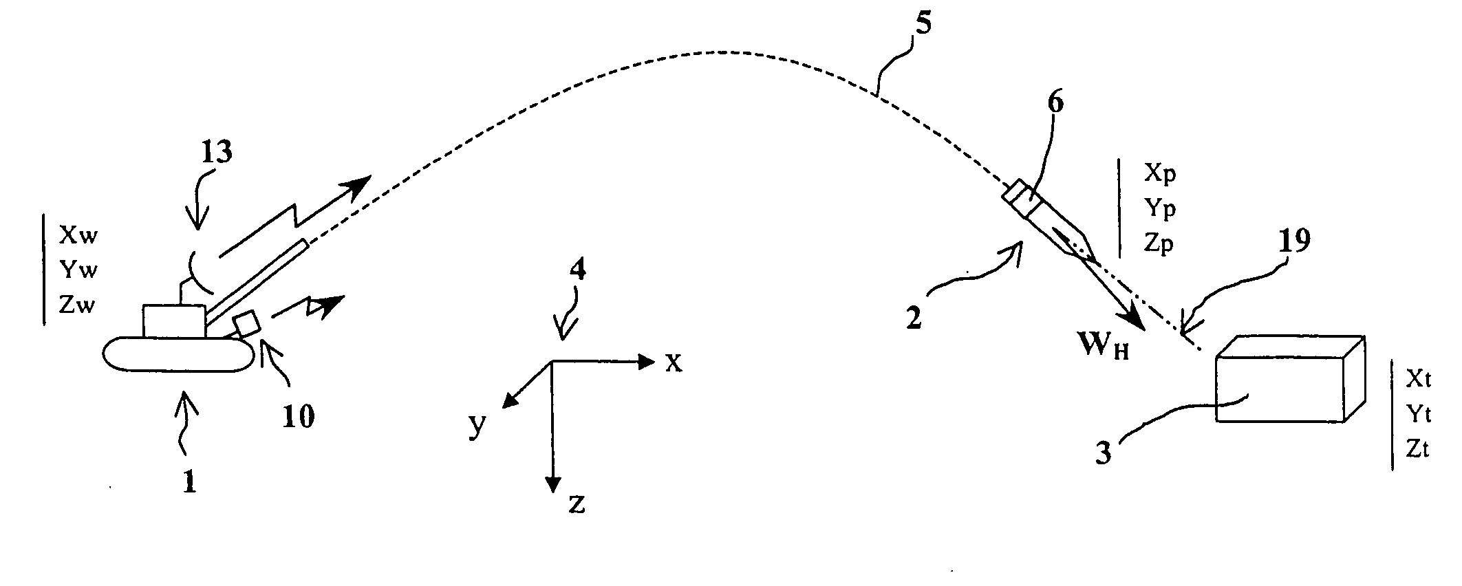
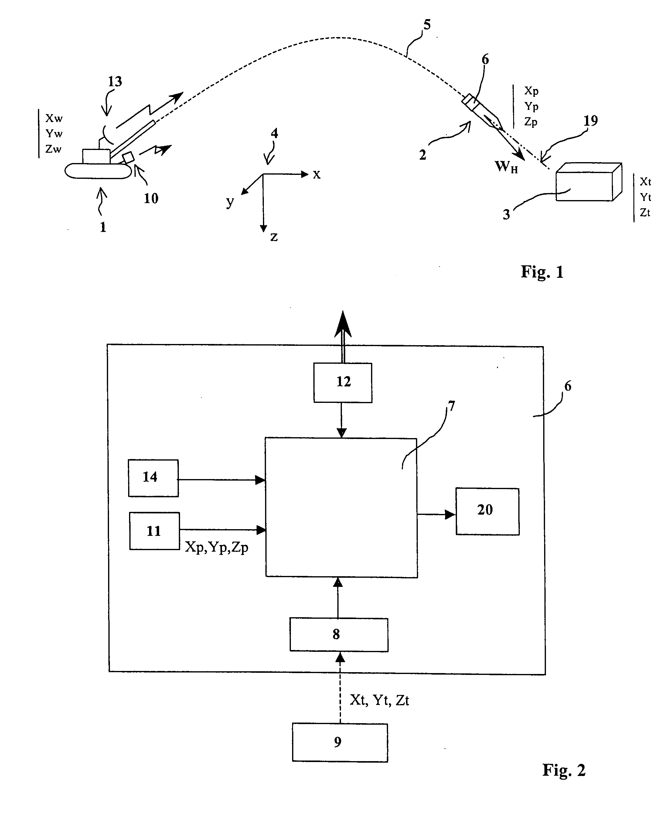
[0047]FIG. 1 shows a weapon system or firing platform 1 (here a self-propelled artillery gun) which is firing a projectile 2 at a target 3 to destroy it. This projectile 2 constitutes an attack module with a pre-determined direction of action WH which here forms an angle with axis 19 of the projectile 2.

[0048]The latter follows a ballistic trajectory 5 and is spinning around its axis.

[0049]FIG. 1 shows a fixed terrestrial reference 4 with axes XYZ. In this reference, the coordinates of the firing platform 1 are XwYwZw, the coordinates of the projectile 2 are XpYpZp, and those of the target 3 are XtYtZt.

[0050]For the sake of clarity, hereafter we will refer to point coordinates (target, platform, projectile). Naturally, the targets under aim occupy a certain surface area on the ground and the target point corresponds, for example, to the barycentre of the actual target. Similarly, the projectile's coordinates are, for example, those of its centre of gravity, or else those of the seat...


PUM


Abstract

The invention relates to a process to control the initiation of an attack module (2), such as a projectile or sub-projectile, such attack module having at least one pre-determined direction of action (WH), such process wherein it has the following steps: before firing or on trajectory, the coordinates of at least one target (3) are programmed into a fixed terrestrial reference (4), the orientation of the direction(s) of action (WH) in the fixed terrestrial reference (4) is determined at least once on trajectory and the initiation of the attack module (2) is only authorized if the direction of action (WH) is oriented in the direction of the target (3).The invention also relates to the device implementing such a process.

Description

BACKGROUND OF THE INVENTION[0001]1. Field of the Invention[0002]The technical scope of the invention is that of devices to initiate an attack module which has at least one predetermined direction of action.[0003]2. Description of the Related Art[0004]By attack module having a predetermined direction of action, we mean a projectile or sub-projectile which acts preferentially in a given direction in space.[0005]This is the case for projectiles or sub-projectiles incorporating a shaped charge (hollow charge or explosively-formed charge). In this case, the direction of action is that in which the slug or jet of the shaped charge is projected. By way of an example, patent FR2793314 discloses a known sub-projectile with an explosively-formed charge.[0006]It is also the case for projectiles or sub-projectiles which are splinter-forming and are designed so as to project splinters in a given mean direction. It is known, for example, to replace the charge liner of an explosively-formed charge...

Claims


Application Information

Patent Timeline
Patent Type & Authority Applications(United States)
IPC IPC(8): F42B15/01
CPCF41G7/34F42C15/40F42C13/006F41G7/346
Inventor BREDY, THIERRY
Owner NEXTER MUNITIONS
Learn More