Muffler hanger

a technology of mufflers and hangers, which is applied in the direction of machine/engines, other domestic objects, machine supports, etc., can solve the problems of increased number of parts, creased problems in ride comfort of vehicles, and suffers in ride comfort for passengers in cabins, so as to ensure durability of outer stopper parts, ensure the durability of connecting parts, and ensure the effect of space utilization

Active Publication Date: 2009-01-01
HONDA MOTOR CO LTD +1
View PDF32 Cites 13 Cited by
  • Summary
  • Abstract
  • Description
  • Claims
  • Application Information

AI Technical Summary

Benefits of technology

[0041]Preferably, the rubber annular portion has an outside peripheral shape of ellipsoidal, and an inside peripheral shape of rectangular. (Sixth Mode). This arrangement makes it possible to give the largest vertical dimension of the outer stopper portions at the center in the vehicle left-right direction, resulting in ensuring durability of the outer stopper portions. In this arrangement, the parts of the rubber annular portion, which are opposed to each other in the left-right direction have the largest horizontal dimension at the center in the vertical direction. Thus, if the rubber arm is connected to the rubber annular portion at the center of the rubber annular portion in the vertical direction, the present arrangement ensures durability of the connecting portions between the rubber arm and the rubber annular portion. Additionally, when the second mounting holes are formed at vertically center portions of the horizontally opposite parts of the rubber annular portions, respectively, the second mounting holes can be formed with a sufficient space utilization.
[0042]In another preferred practice, a minimum thickness in a vehicle front-back direction of the outer stopper portions is greater than a minimum thickness in the vehicle front-back direction of parts of the rubber arm which are disposed between the first mounting hole and the second mounting holes (Seventh Mode). This arrangement makes it possible to provide soft spring characteristics of the rubber arm, while ensuring sufficient durability of the outer stopper portions of the rubber annular portion as well as sufficient shape stability of the rubber annular portion.
[0043]In another preferred practice, each of the first mounting hole and the second mounting holes is designed such that both axial open ends thereof are tapered portions having a diameter gradually increasing toward the open end, and an axially medial part thereof has a diameter smaller t

Problems solved by technology

However, elastically supporting the muffler 222 in this way requires the use of two of the muffler hangers 200, resulting in the problem of an increased number of parts.
Also, this muffler 222 creases problems in terms of ride comfort of the vehicle, owing to weak bearing force with respect to motion (swaying) of the muffler 222 in the vehicle left-right direction.
The movement of the muffler 222 at this time will be transmitted with a delay to the vehicle body, and ride comfort for the persons on the cabin will suffer as a result.
However, in the case of the muffler hanger 224 with the metal fitting shown in FIG. 7, since the metal fitting 226 is one of the required components, in the process of manufacture of the muffler hanger 224 a vulcanization bonding step will be necessary in order to bond the metal fi

Method used


Image

  • Muffler hanger
  • Muffler hanger
  • Muffler hanger

Examples


Embodiment Construction

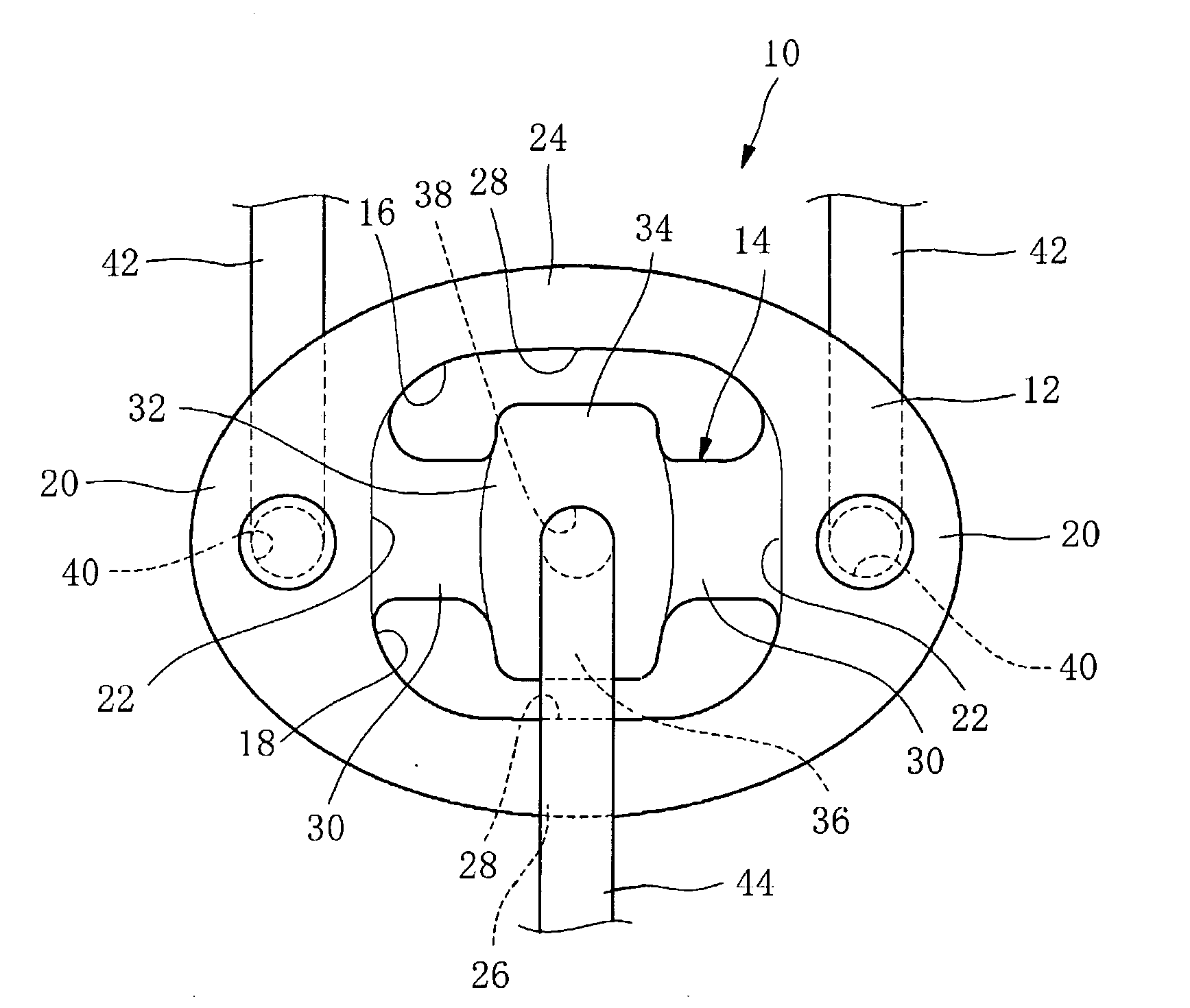
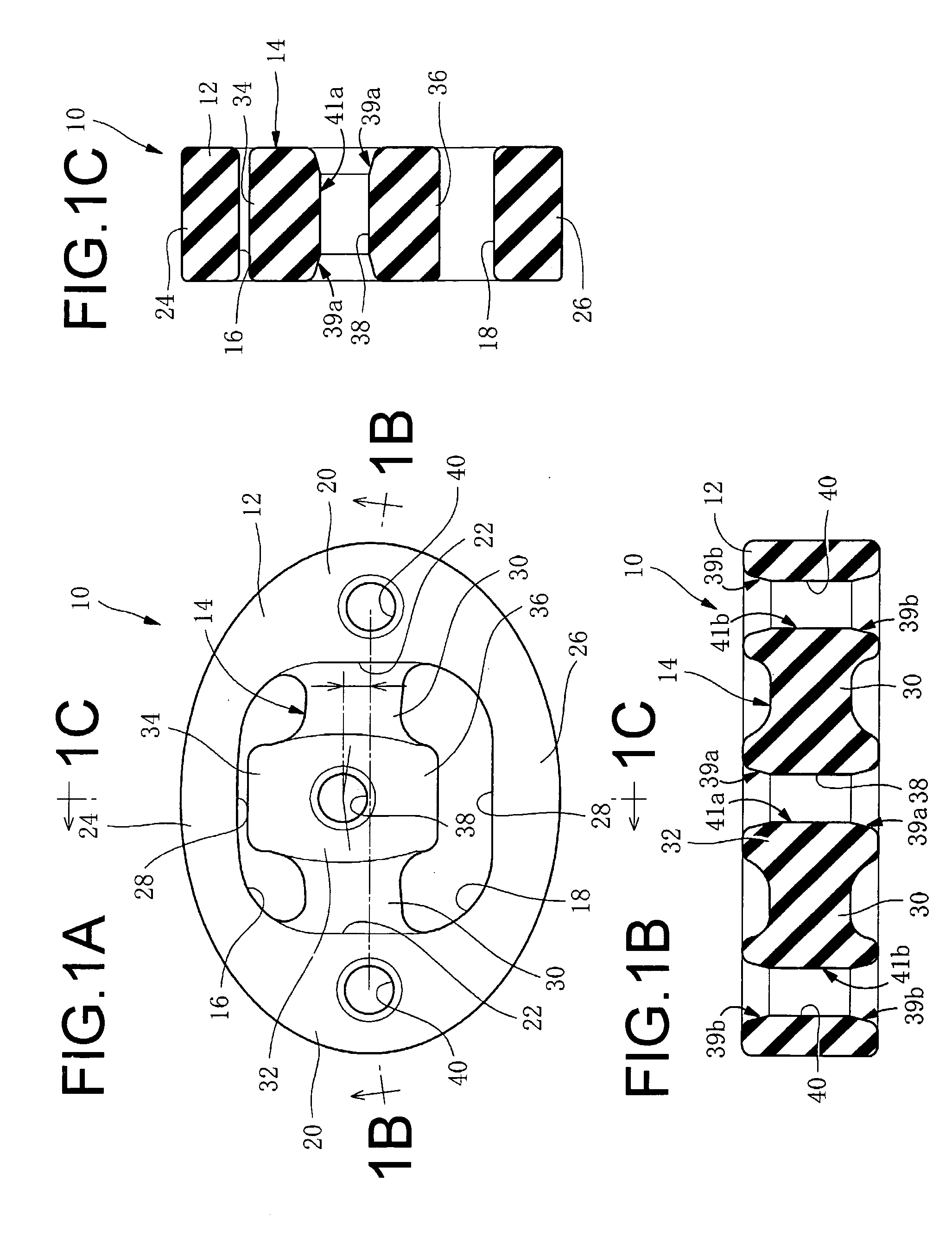
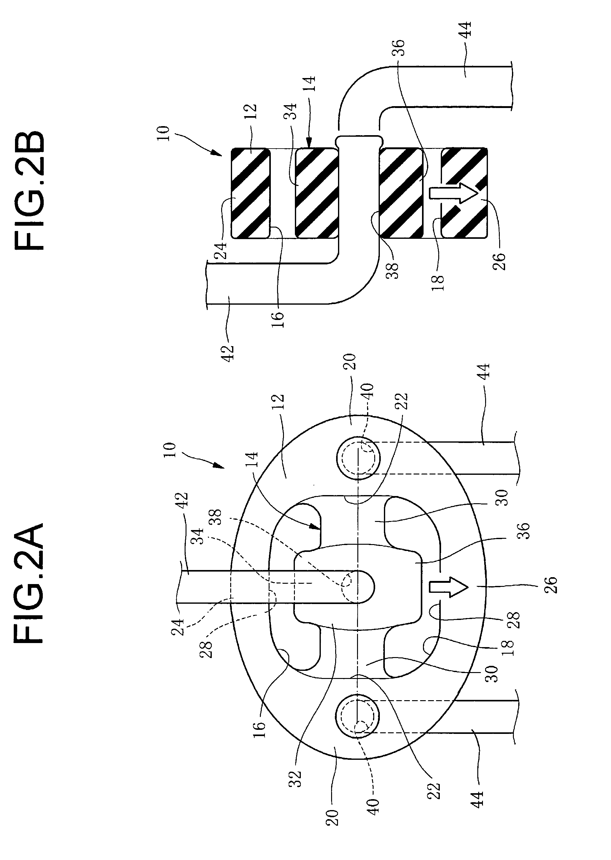
[0055]FIGS. 1A-1C depict a muffler hanger 10 according to the embodiment, shown prior to installation in the vehicle. In FIG. 1A, the vertical direction in the drawing coincides with the actual vertical direction of the vehicle, and the left-right direction in the drawing coincides with the actual left-right direction of the vehicle.

[0056]The muffler hanger 10 according to the embodiment is composed of a rubber elastic body which includes a rubber annular portion 12 of continuous ring shape in the circumferential direction, a single rubber arm 14 which interconnects vertically-medial regions of the rubber annular portion 12 in left-right direction, and an upper space 16 and a lower space 18 formed above and below the arm. The rubber arm 14 constitutes an elastic support portion for the muffler, and is integrally formed with the rubber annular portion 12 so as to extend in the left-right direction.

[0057]The rubber annular portion 12 has a peripheral shape of horizontally elongated el...


PUM


Abstract

A muffler hanger including: a rubber annular portion; a rubber arm constituting an elastic support portion for the muffler; an upper space and a lower space for permitting deformation of the rubber arm; a first mounting hole disposed in a center of the rubber arm in a vehicle left-right direction to extend in a vehicle front-back direction when installed on the vehicle, and attached in a mated condition to a support pin provided on one of a muffler side and a vehicle body side; and a pair of second mounting holes disposed at locations away to right and left sides from the first mounting hole to extend in the front-back direction, and attached in a mated condition to support pins on the other side. The first and second mounting holes are arranged to form a row in the left-right direction, with positional relationships such that when installed on the vehicle the holes overlaps one another as viewed in the left-right direction.

Description

BACKGROUND OF THE INVENTION[0001]1. Field of the Invention[0002]This invention relates to a muffler hanger adapted for elastically suspending the muffler of the exhaust system of an automotive vehicle, and for absorbing vibration between the muffler and the vehicle body.[0003]2. Description of the Related Art[0004]The function of a muffler hanger of this kind is to prevent up-and-down or vertical vibration of the exhaust system components, including the muffler and exhaust pipe, from being transmitted over to the vehicle body, while at the same time providing elastic support to the suspended muffler. In order to satisfactorily realize this function, the conventional muffler hangers have been designed so as to minimize as much as possible its spring rigidity in the vertical direction, i.e. to make the muffler hangers as flexible as possible in the vertical direction.[0005]FIG. 5 depicts by way of specific example the design disclosed in U.S. Pat. No. 5,050,837. In FIG. 5, 200 denotes...

Claims


Application Information

Patent Timeline
IPC IPC(8): F16M13/00
CPCB60K13/04F01N13/1822F16L55/035F16F1/373F16F1/371
Inventor ENDO, MASAMI
Owner HONDA MOTOR CO LTD
Why Eureka
Try Eureka