

Magnetic Field Sensing Element
a magnetic field and sensing element technology, applied in the direction of magnetic field measurement using galvano-magnetic devices, instruments, plasma techniques, etc., can solve the problems of high cost design and equipment, high cost, and high cost of transducer technology, and achieve the effect of detecting time-dependent magnetic fields
Inactive Publication Date: 2009-01-01
IEE INT ELECTRONICS & ENG SA
View PDF4 Cites 28 Cited by
- Summary
- Abstract
- Description
- Claims
- Application Information
AI Technical Summary
Benefits of technology
The invention introduces a new type of magnetic field sensor that combines solid state effects with nanometer-scale precision. This sensor is simpler and less expensive to produce than previous versions.
Problems solved by technology
They use inductive coils and can only detect a time dependent magnetic field.
Although these technologies based on effects at the nano-scale can today be implemented at industrial level, they require sophisticated thin film technology, which involves high cost design and equipment.
In addition, despite their large range of possibilities to determine the presence, range and direction of a magnetic field, this is only possible at the position where the sensing element is located.
Again, this transducer requires sophisticated and expensive thin film technology, and its functionality is limited by its deterministic construction which closely relates the physical properties of the nanoparticles with their preparation conditions and the sensor build-up.
Method used
View moreImage
Smart ImageViewing Examples

Examples
first embodiment
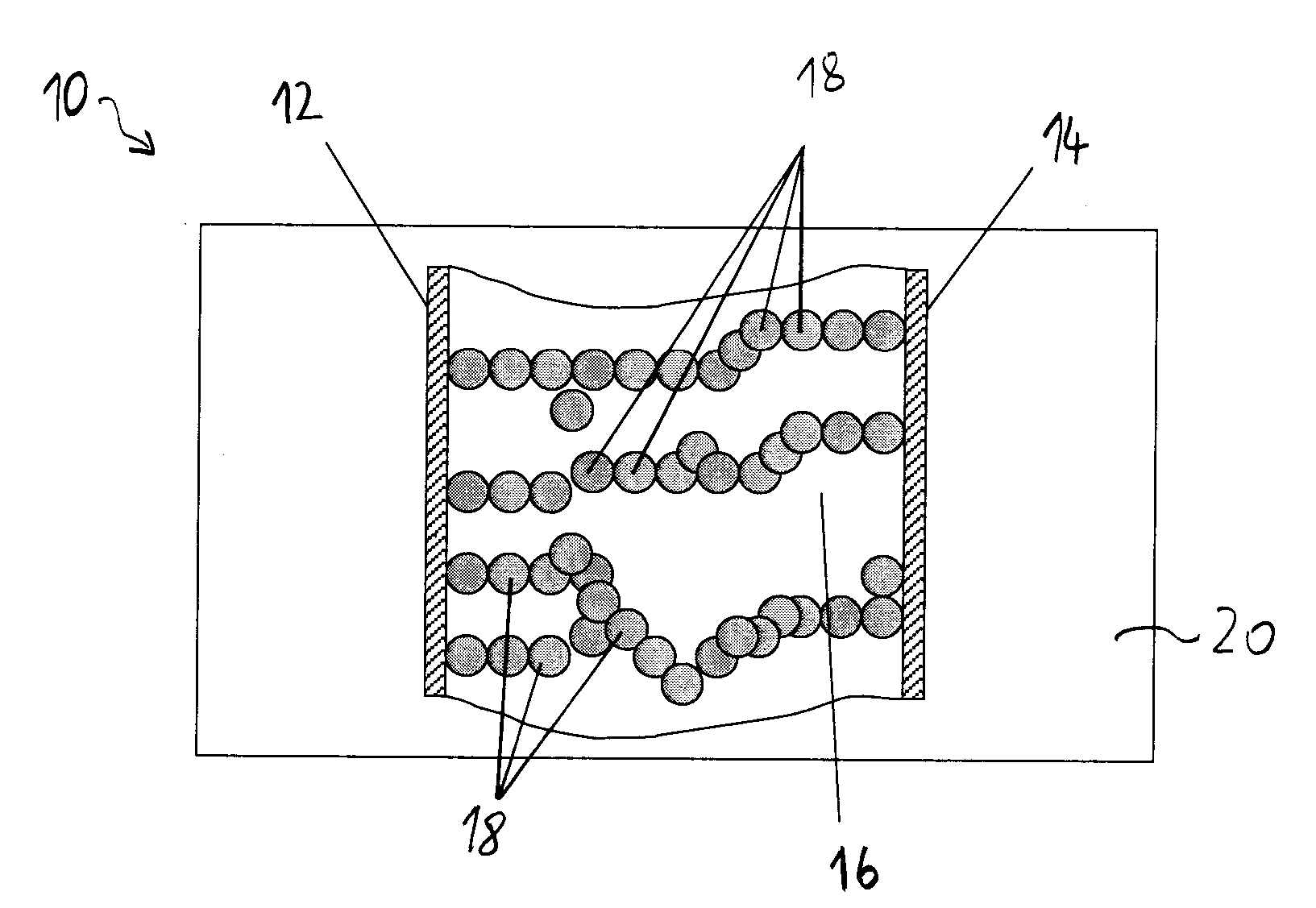
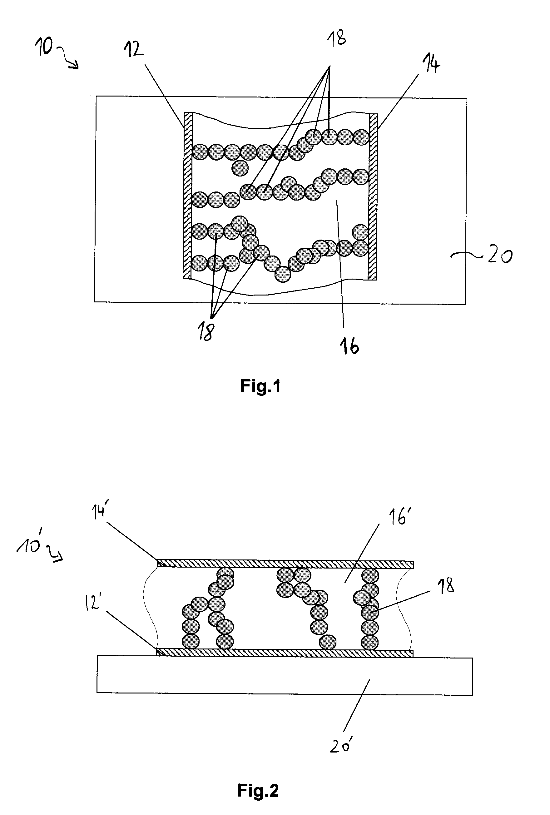
[0047]FIG. 1: is a section view, along a plane parallel to the substrate, through a magnetic field sensing element according to the invention;
second embodiment
[0048]FIG. 2: is a section view, along a plane perpendicular to the substrate surface, through a magnetic field sensing element according to the invention;
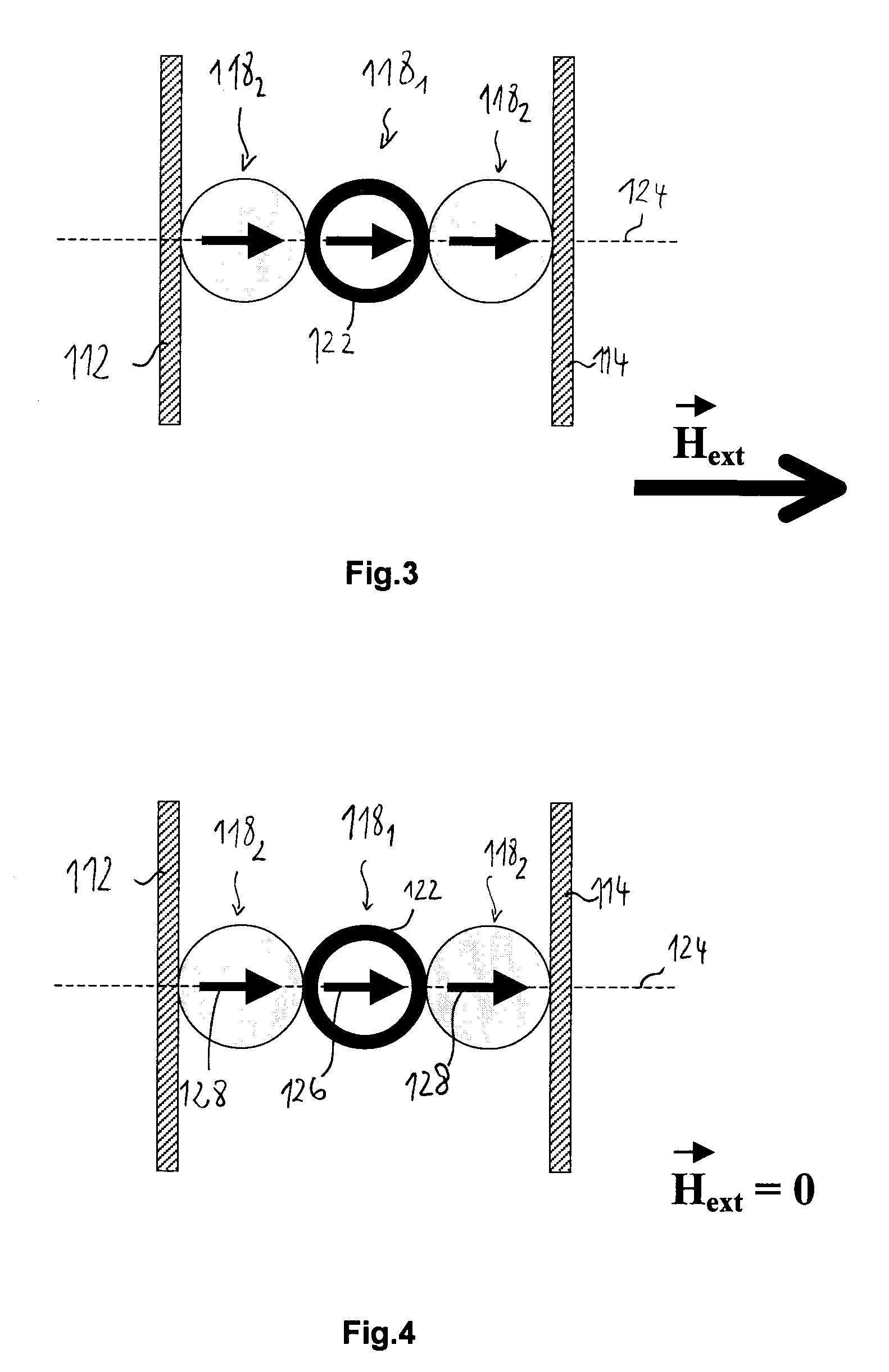
[0049]FIGS. 3, 4 and 5 are sketches illustrating the working principle of the present magnetic field sensing element based on an exemplary embodiment featuring 3 nanoparticles.
Login to View More PUM
 Abstract
A magnetic field sensing element includes a pair of electrodes; a dielectric polymer layer separating the electrodes; and a network of magnetic nanoparticles in the insulating layer forming a current flow path between the electrodes; where the network of magnetic nanoparticles includes at least one magnetic tunnel junction involving two neighbouring nanoparticles of different coercivity.
Description
TECHNICAL FIELD OF THE INVENTION[0001]The invention generally relates to a magnetic field sensing element. More precisely, it relates to a magnetic field sensing element which utilizes the phenomenon of tunneling magneto resistance.BRIEF DISCUSSION OF RELATED ART[0002]Today, numerous kinds of magnetic field sensors are available. They differ in the technology on which they are based, which often also depends on the field of application.[0003]The most conventional electromechanical magnetic field sensors are based on the induction principle. They use inductive coils and can only detect a time dependent magnetic field.[0004]For application in the automotive industry for example, magnetic field sensors have been developed that allow detecting and measuring of the presence, the strength and / or variations of magnetic fields. The predominant technologies used in such sensors are based on the well known Hall-effect and the magneto resistive effect. These technologies conventionally involve...
Claims
Login to View More Application Information
Patent Timeline
 Patent Type & AuthorityApplications(United States)
IPC IPC(8): G01R33/06H05H1/48H10N50/10H10N50/01
CPCG01R33/06H01L43/12H01L43/08H10N50/10H10N50/01
InventorWITTKOWSKI, THOMAS
OwnerIEE INT ELECTRONICS & ENG SA