Display device

a display device and display technology, applied in the field of display devices, can solve the problems of inconvenient carrying of the mouse, occupying space, and difficulty in disposing of the numerous icons thereon, and achieve the effects of facilitating operation, reducing noise from the outside environment, and reducing the number of display devices

Active Publication Date: 2009-01-01
PANASONIC LIQUID CRYSTAL DISPLAY CO LTD +1
View PDF24 Cites 66 Cited by
  • Summary
  • Abstract
  • Description
  • Claims
  • Application Information

AI Technical Summary

Benefits of technology

[0013]In the present invention, specified functions can be selected by touching the substrate corresponding to photosensors disposed outside the effective screen; consequently, operation is facilitated. Accordingly, the present invention has the superior merit of allowing necessary functions to be used even by persons who are not accustomed to the operation of mobile telephones or the like.
[0014]Correction sensors are installed in the vicinity of the photosensors; accordingly, erroneous operation of the photosensors caused by

Problems solved by technology

However, in mobile telephones and the like, the screen is small; therefore, it is difficult to dispose numerous icons thereon.
Furthermore, carrying a mouse is inconvenient for the user, and a function that causes a pointer to move by sliding the fingers instead of using

Method used


Image

  • Display device
  • Display device
  • Display device

Examples


example 1

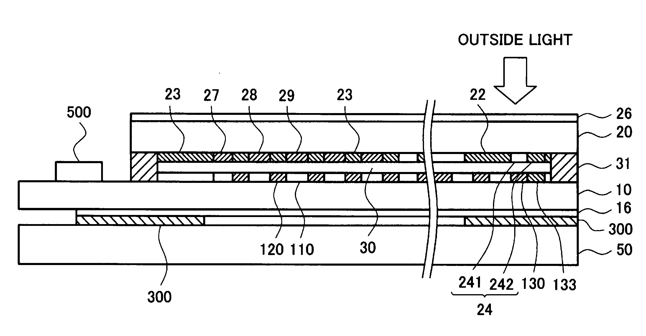
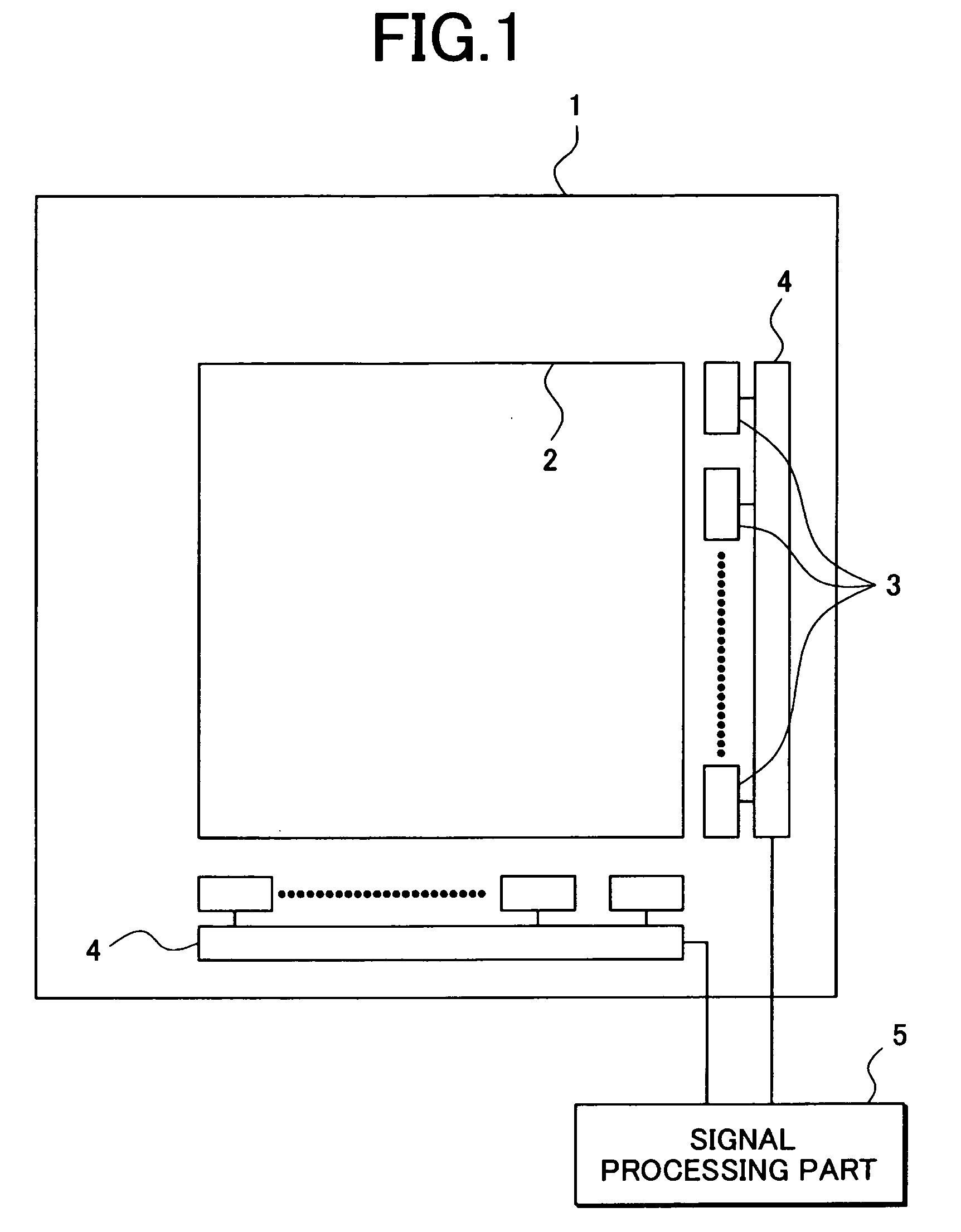
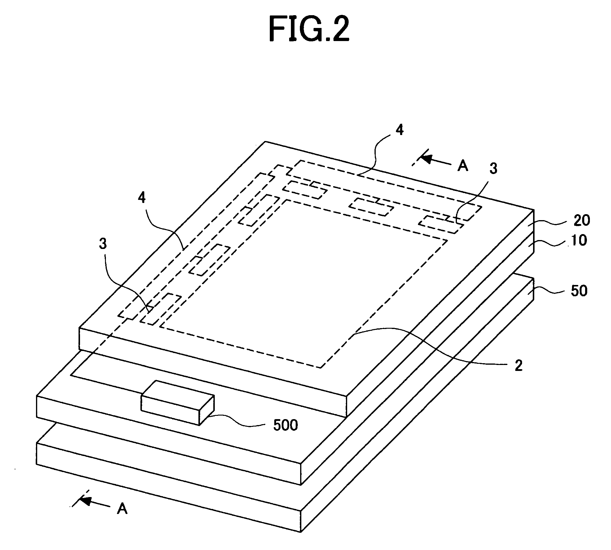
[0040]FIG. 2 is a perspective view showing an example (Example 1) in which the present invention is applied to a liquid crystal display device. FIG. 3 is a schematic sectional view of a liquid crystal display device showing a section along line A-A in FIG. 2. The liquid crystal display device comprises a liquid crystal display panel and back lighting 50. The liquid crystal display panel comprises a TFT substrate 10 on which TFTs for controlling the pixels, pixel electrodes, and the like are formed, a color filter substrate 20 on which color filters and the like are formed, and a liquid crystal which is sandwiched between these substrates. The liquid crystal 30 is sealed between the TFT substrate 10 and the color filter substrate 20 by a sealing member 31.

[0041]The back lighting 50 comprises a light source such as an LED or the like, and a variety of optical sheets which concentrate light in the direction of the liquid crystal display panel. The light from the back lighting 50 is con...

example 2

[0088]In this example, the photosensor TFTs 130 used as photodiodes have a construction similar to that of the pixel part TFTs 120, and also offer the advantage of allowing manufacture by the same process. However, compared to cases in which these are manufactured exclusively for use as photosensors, there may be instances in which the photo-sensitivity is insufficient. In Example 2, the amount of change in the photo-electric current can be detected more easily in such cases as a result of photosensor TFTs 130 being connected in parallel.

[0089]FIG. 17 shows an equivalent circuit of the photosensor part 3 in Example 2. In the equivalent circuit shown in FIG. 17, photosensor TFTs 130 used as photodiodes are connected in parallel, and correction sensor TFTs 133 are connected in series with the respective photosensor TFTs 130. The photosensor TFTs 130 and the correction sensor TFTs 133 connected in series with the photosensor TFTs 130 are disposed in close proximity to each other, and t...

example 3

[0092]As is shown in FIG. 8, the display device of the embodiment of the present invention is a display device in which photosensor TFTs 130 are disposed in correspondence with photosensor windows (windows 24) formed on the outside of the effective screen part 2, and the variation in the light by touching the windows 24 with a finger is detected. In this case, if the windows 24 are large, noise tends to be picked up. For example, even in cases where the sensor part 3 for selecting another function is touched with a finger, there may be instances in which the shadow of the fingers or the like is detected, and a signal is output. On the other hand, in cases where the windows 24 formed in the photosensor parts 3 are large, there may be a problem in terms of the deterioration of the external appearance of the display as a whole as a result of the generation of reflected light from the metal electrodes, e.g., gate electrodes, source electrodes, drain electrodes, and the like, formed in t...


PUM


Abstract

It is an object of the present invention to allow a specified function to be readily selected in a mobile telephone or the like without performing a complicated operation. A liquid crystal (30) is sandwiched between a TFT substrate (10) and a color filter substrate (20). A photosensor TFT (130) for selecting the function is disposed on the periphery of an effective screen of the TFT substrate (10). A window (24) is provided in a portion of the color filter substrate corresponding to the photosensor TFT (130), and the outside light is blocked as a result of the user touching a finger to the window. A signal from the photosensor is used for selecting the function. A correction sensor TFT (133) is disposed adjacent to the photosensor TFT (130), to thereby eliminating noise caused by the temperature distribution, stray light, or the like, and erroneous operation of the photosensor is prevented.

Description

CROSS-REFERENCE TO RELATED APPLICATION[0001]The present application claims priority from Japanese application JP2007-151571 filed on Jun. 7, 2007, the content of which is hereby incorporated by reference into this application.BACKGROUND OF THE INVENTION[0002]1. Field of the Invention[0003]The present invention relates to a display device, and more particularly to a display device in which a photosensor is disposed on the outside of an effective screen, and means is provided for selecting a display function using this photosensor.[0004]2. Description of the Related Art[0005]Flat panel displays such as liquid crystal display devices and the like are widely used in mobile telephones and the like. In recent years, mobile telephones in particular have shown an increase in functionality, and in cases where certain operations are performed, depending on the function, it may be necessary to perform numerous selections from the menu selection screen until the desired function is reached. It ...

Claims


Application Information

Patent Timeline
IPC IPC(8): G06F3/042
CPCG06F3/0412G06F3/042H01L27/3244H01L27/323H01L27/3227H10K59/60H10K59/40H10K59/12
Inventor SAITO, TERUAKISATO, HIDEONISHITANI, SHIGEYUKI
Owner PANASONIC LIQUID CRYSTAL DISPLAY CO LTD
Why Eureka
Try Eureka