
System and method for manipulating and processing materials using holographic optical trapping

Inactive Publication Date: 2009-01-01
ARRYX INC
View PDF19 Cites 7 Cited by
  • Summary
  • Abstract
  • Description
  • Claims
  • Application Information

AI Technical Summary

Benefits of technology

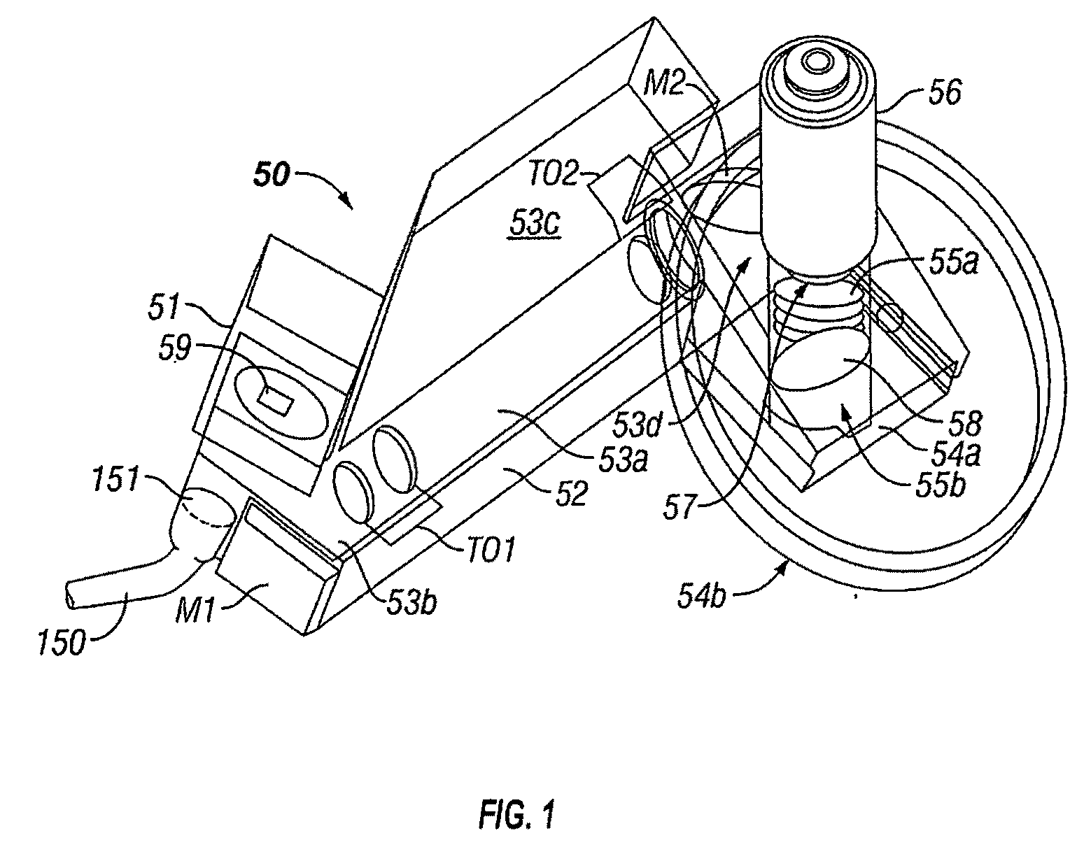
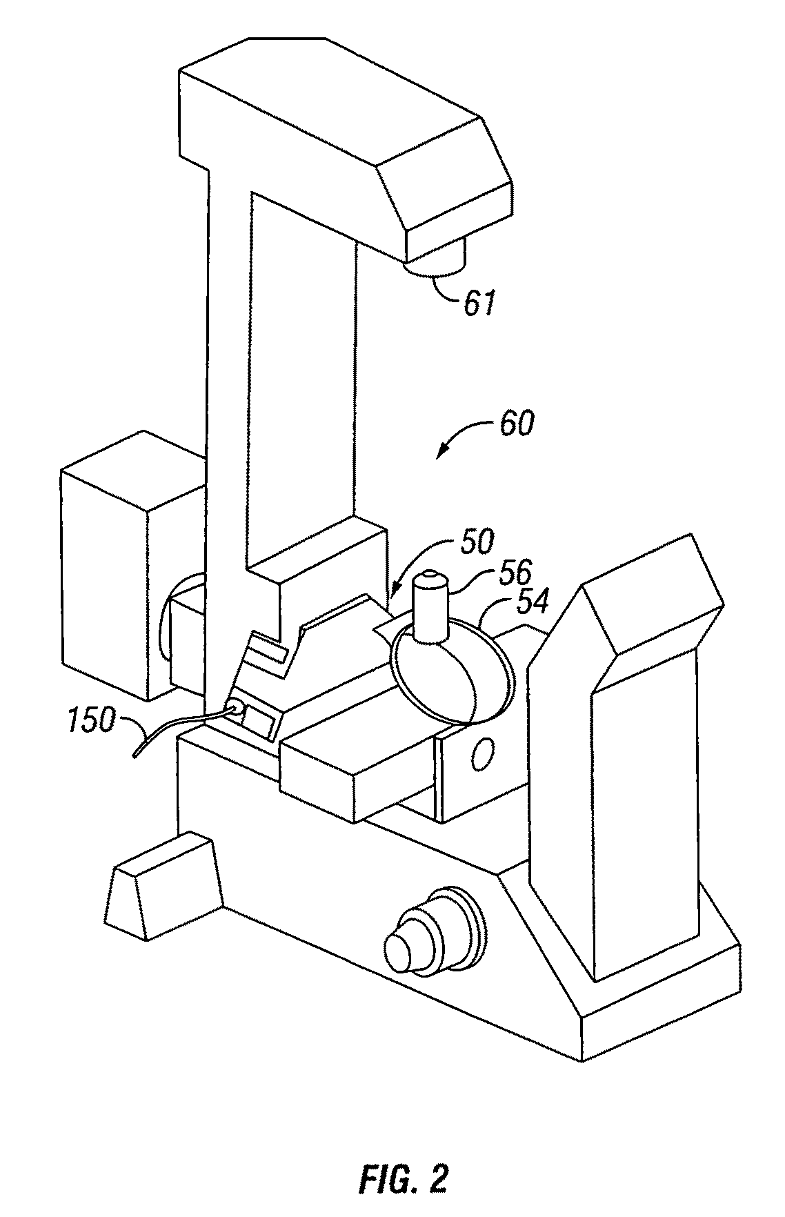
[0040]A system and method consistent with the present invention allows various industrial polymers and biopolymers to be attached to nanotubes and nanostructures. These polymers may in turn be attached to functionalized colloidal spheres. The spheres facilitate manipulation of the nanostructures with optical tweezers. In addition, holographic optical trapping may then be employed to pattern and control large quantities of nanostructures both on and off substrates.
[0041]Systems and methods consistent with the present invention employing holographic optical trapping enable and enhance a variety of techniques for manipulation and processing of nanomaterials and nanostructures.
[0042]An exemplary embodiment of the present invention comprises a method for controlling nanotubes using a cloud of optically trapped nanospheres which facilitate manipulation and patterning of the tubes. Holographic optical trapping confers distinct advantages in this area because the shapes of the traps may be intricately sculpted, allowing detailed control of the cloud of nanospheres which in turn allows much more versatile manipulation of the nanotubes.

Problems solved by technology

There are widely acknowledged challenges in the development of many of these technologies.
One challenge involves the separation or purification of nanomaterials based on structural properties such as clarity, diameter, length, and other properties.
Another serious challenge involves the manipulation of nanomaterials for controlled assembly, deposition, and orientation.
Although methods exist for certain types of deposition, the capability to move single objects in three dimensions and to pattern large groups of objects is still lacking.

Method used


Image

  • System and method for manipulating and processing materials using holographic optical trapping
  • System and method for manipulating and processing materials using holographic optical trapping
  • System and method for manipulating and processing materials using holographic optical trapping

Examples


Embodiment Construction

[0081]Particular embodiments of the invention are described below in considerable detail for the purpose of illustrating its principles and operation. However, various modifications may be made, and the scope of the invention is not limited to the exemplary embodiments described below. For example, although the invention is described by using nanomaterials and sometimes micromaterials as the exemplary embodiments, it should be understood that the invention has applications over a broad range of materials sizes from the micro regime around 1 mm or less down to the pico regime around 0.1 nm, and it is intended that such applications are included in the invention.

[0082]As used herein, the term nano refers to particles, materials and structures which have a characteristic size in the nano region, i.e. particles having a sub-micron characteristic dimension of less than 10−6 m. These particles may be atoms, molecules, agglomerations of such atomic, and molecular materials and elemental ma...


PUM


Abstract

An apparatus for manipulating particles (micro, nano, and pico) having one or more characteristics with an optical trap formed by modulating a laser beam with a Diffractive Optical Element (DOE). At least one characteristic of the material is selected; and a laser beam having a selected wavelength corresponding to the at least one selected characteristic of the material is generated. Values of the DOE are calculated corresponding to the at least one selected characteristic of the material. The beam and the DOE are modulated to produce a holographic optical trap having properties corresponding to the at least one selected characteristic; the trap is focused to a beam focus or selected spot size; and the beam focus is located near a particle location for trapping the particle therein.

Description

CROSS REFERENCE TO RELATED APPLICATIONS[0001]This application is a Continuation-in-part of U.S. application Ser. No. 10 / 974,975, filed Oct. 28, 2004.[0002]The present invention is related to the following provisional applications:[0003]60 / 543,488, filed Feb. 11, 2004.[0004]60 / 519,407, filed Nov. 12, 2003.[0005]60 / 515,091, filed Oct. 28, 2003[0006]60 / 515,092, filed Oct. 28, 2003[0007]60 / 531,254 filed, Dec. 20, 2003[0008]The present invention claims priority to the following provisional applications:[0009]60 / 554,061 filed, Mar. 17, 2004[0010]60 / 554,524 filed, Mar. 19, 2004[0011]The teachings of the applications identified above are incorporated herein by reference.BACKGROUND OF THE INVENTION[0012]The present invention relates to a system and method for manipulating and processing nanomaterials, micromaterials and picomaterials using holographic trapping.[0013]Nano materials may be generally described as materials and structures characterized as having at least one dimension in the nan...

Claims


Application Information

Patent Timeline
IPC IPC(8): G03H1/04G02F1/29G02B27/40G21K1/00H05H3/04
CPCB82Y10/00G03H1/08G03H2225/32G03H2001/0077G03H1/2294
Inventor PLEWA, JOSEPHTANNER, EVANMUETH, DANGRUBER, LEWISBRADLEY, KENNETH
Owner ARRYX INC
Learn More