Non-Contact Power Supply System

Active Publication Date: 2009-01-01
DAIFUKU CO LTD
View PDF16 Cites 41 Cited by
  • Summary
  • Abstract
  • Description
  • Claims
  • Application Information

AI Technical Summary

Benefits of technology

[0008]According to the configuration of the present invention, the power supply unit determines a phase difference between the output current fed to the induction lines and the rectangular wave signal based on the output current and power consumption measured by the measuring unit, and the rectangular wave signal for driving transistors is corrected according to the phase difference relative to the command signal and then outputted, so

Problems solved by technology

Further, when the phase difference reaches 180°, electromotive force induced to the pickup coil is generated in opposite directions, power feeding is disabled, and the outputs of two power supply units are short-circuited through the pickup coil, resulting in overcurrent or the like.
However, such a conventional non-contact power supply system requires a current transformer (CT) for a wide frequency domai

Method used


Image

  • Non-Contact Power Supply System
  • Non-Contact Power Supply System
  • Non-Contact Power Supply System

Examples


Embodiment Construction

[0019]Embodiments of the present invention will be discussed below in accordance with the accompanying drawings.

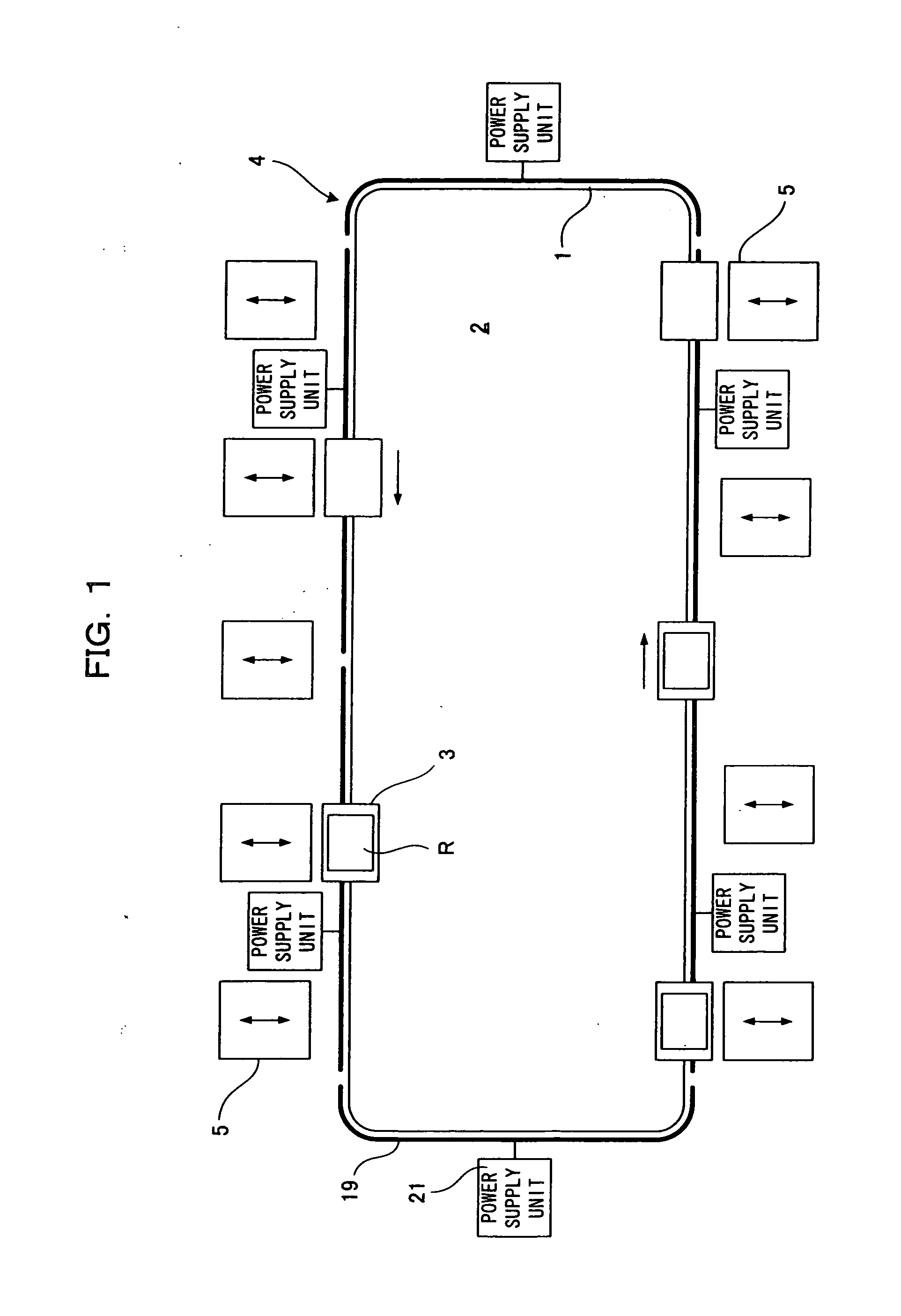
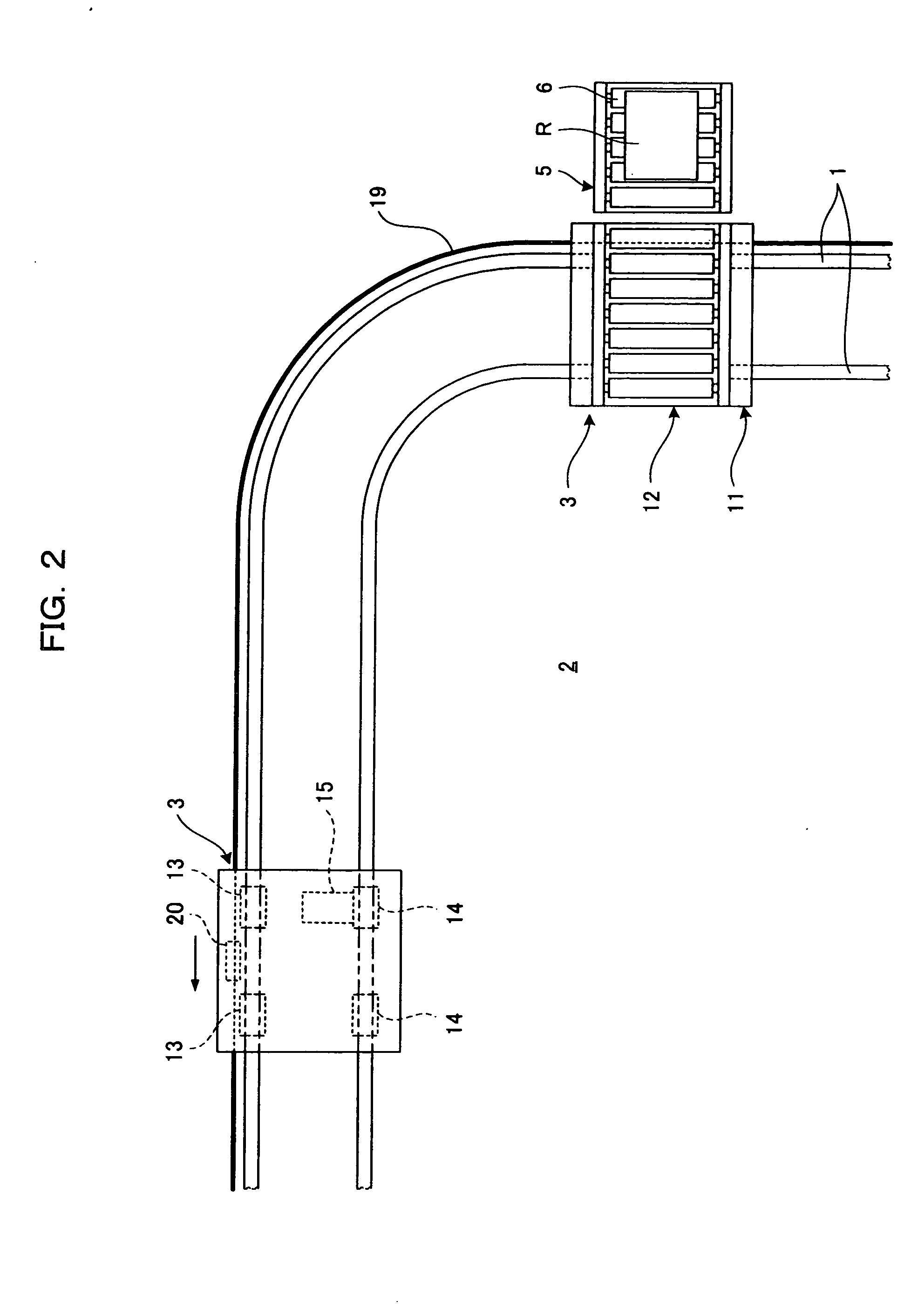
[0020]FIG. 1 is a travel path diagram showing an article transport apparatus including a non-contact power supply system according to an embodiment of the present invention. FIG. 2 is a principle part structural diagram showing the article transport apparatus.

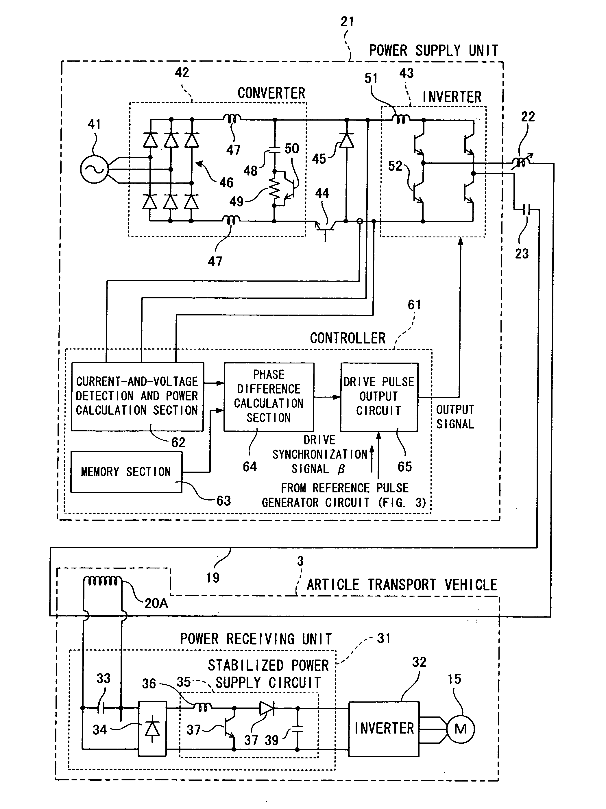
[0021]In FIGS. 1 and 2, reference numeral 1 denotes a pair of transport rails arranged on a floor 2 and reference numeral 3 denotes a four-wheel article transport vehicle (an example of a moving body) which travels by itself and transports an article R while being guided along the transport rails 1. The total number of the article transport vehicles 3 is five.

[0022]The transport rails 1 make up a transport path (an example of a moving path) 4 shaped like a loop (ring). A plurality of (nine in FIG. 9) stations (article receiving units) 5 are placed along the transport path 4. The article transport vehicles 3 travel alo...


PUM


Abstract

A non-contact power supply system is provided in which current phases of induction lines are matched. According to the output current of a power supply unit (21) and the power consumption of induction lines (19), a lead time corresponding to a phase difference between the output currents of the induction lines is determined. A signal for driving transistors (52) is advanced ahead of a drive synchronization signal (β) according to the lead time.

Description

TECHNICAL FIELD[0001]The present invention relates to a non-contact power supply system in which induction lines fed with high-frequency current of a predetermined frequency are placed along the moving path of a moving body, a pickup coil is provided in the moving body to face the induction lines, and power is fed from electromotive force induced to the pickup coil to a load varying in power consumption in the moving body.BACKGROUND ART[0002]Some conventional non-contact power supply systems have long induction lines. In such a non-contact power supply system, since voltage applied to an induction line is limited, the induction line is divided and each of the divided lines is connected to a power supply unit.[0003]In such a non-contact power supply system, even when power supply units supply high-frequency currents at the same frequency to induction lines, a phase difference occurs between the high-frequency currents. When the pickup coil of a moving body is disposed across the indu...

Claims


Application Information

Patent Timeline
IPC IPC(8): H02M7/48B60L5/00B60M7/00B61B13/00H02J7/00H02J17/00H02M5/458
CPCB60L5/005B60M7/00B60L2200/26H02M5/458H02J5/005H02J50/12H02J50/40H02J50/90
Inventor NUNOYA, MAKOTOTAKEDA, KAZUTOSHI
Owner DAIFUKU CO LTD
Why Eureka
Try Eureka