
Determining correspondence object pairs for medical navigation

Active Publication Date: 2009-01-01
SMITH & NEPHEW INC +2
View PDF5 Cites 4 Cited by
  • Summary
  • Abstract
  • Description
  • Claims
  • Application Information

AI Technical Summary

Benefits of technology

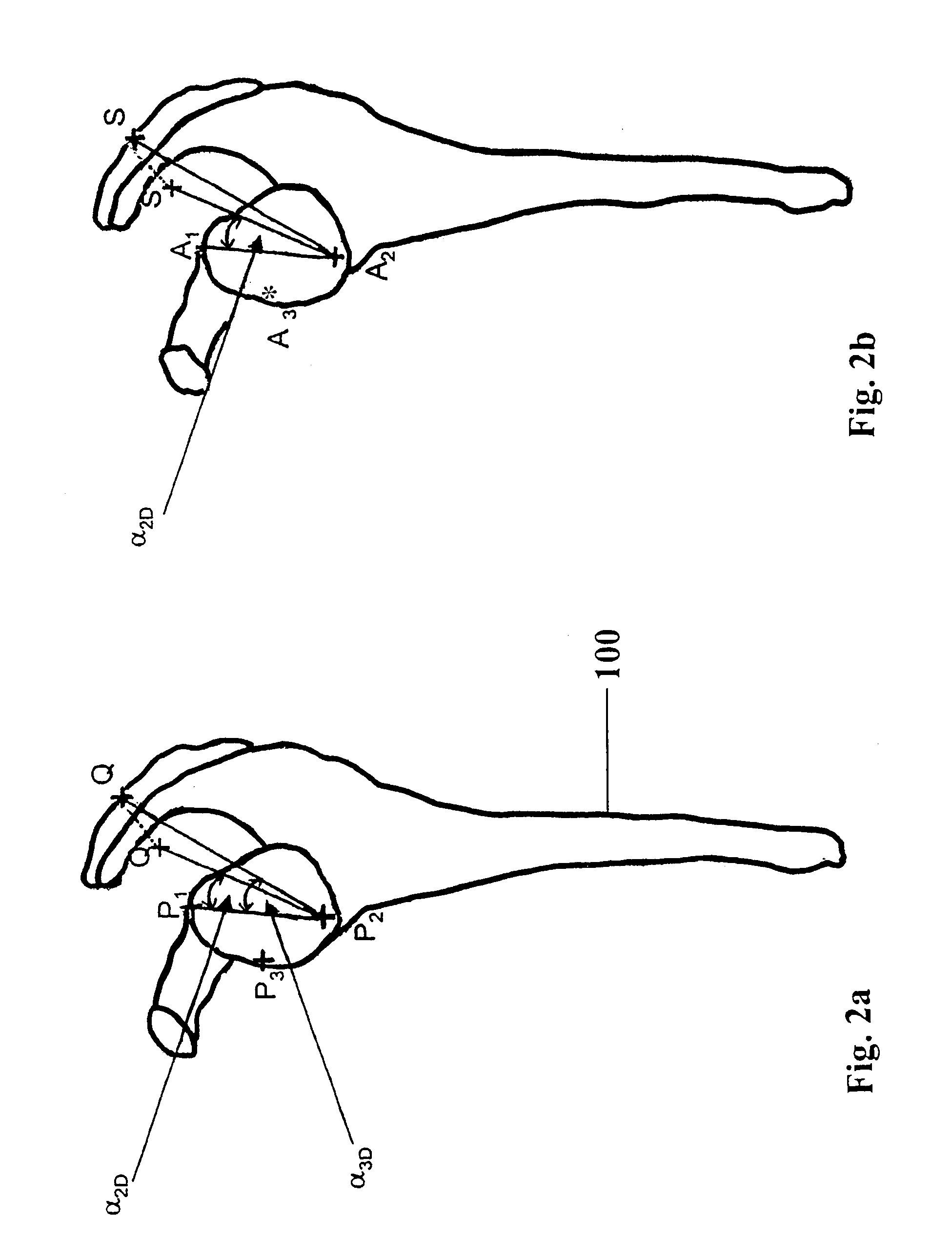
[0013]When changing the position of one of the objects (A-object or B-object) or when replacing an object with a new object, the operator may be assisted by reference information that is based on the comparative data. The position of the other objects that are not to be replaced or changed is assumed to be given, and the reference information gives an indication of the extent to which the relationship data A and the relationship data B correspond. It is possible to indicate (e.g., acoustically) when the two relationship data sets approach each other or move further away from each other with regard to the comparative value. If the object is a virtual object, then based on the geometric relationship data in the actual space, it is possible to display a selection of virtual candidate objects that would correspond to the relationship data in the actual space. For example, if a particular distance is predetermined (as actual relationship data) by two objects in the actual space, and if only one object is predetermined in the virtual space, then candidate objects in the virtual space lie on the surface of a sphere. This sphere is defined by a center that corresponds to the object already determined in the virtual space and a radius that corresponds to the distance between the two objects in the actual space. More specifically, the candidate objects may lie on points or along a line or lines that result from an intersection between the surface of the sphere and the surface of the body structure. The indicated information (for example, a displayed surface of the sphere, or in two dimensions, a circular line or intersection points or intersection lines) may be helpful when the object to be defined lies on a substantially one-dimensional body structure. For example, the object may lie on a ridge-like body structure or on an edge of a body structure, and the surface of the sphere intersects the course and surface of said ridge or the edge at an angle. In this example, the results include punctiform candidate objects between which the operator can then choose. Furthermore, due to a provisional registration between the virtual and actual object (based on the relationship data available) it is possible to display the alignment of the objects on a screen for the operator. It is therefore possible, while the objects are being changed, to facilitate spatial orientation and therefore also make it easier to localize the objects.
[0049]There are many different image data sets, on the basis of which it is possible to navigate. For example, it is possible to navigate based on the registered two-dimensional image data sets (for example, based on the conventional x-ray recordings). It is also possible to navigate based on the registered three-dimensional image data sets that are, for example, generated in a computer tomography (CT) or magnetic resonance (MRT) recording. In the case of three-dimensional image data sets, the surgeon may be shown sectional representations through different planes. Virtual body structure data (that has been pre-operatively obtained) likewise may be accurately registered by comparing the actual reference frame with the virtual reference frame, and used in navigation.

Problems solved by technology

In reality, determining the landmarks can be difficult.
In other words, if the surface structure of the bone is not prominent, landmark determination can become uncertain.

Method used


Image

  • Determining correspondence object pairs for medical navigation
  • Determining correspondence object pairs for medical navigation
  • Determining correspondence object pairs for medical navigation

Examples


Embodiment Construction

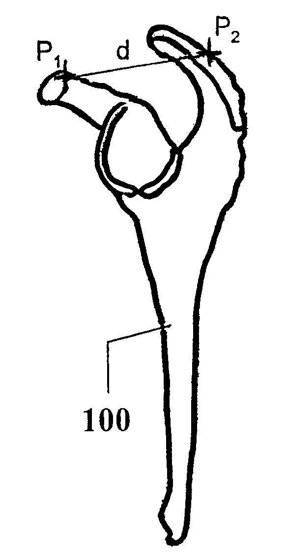
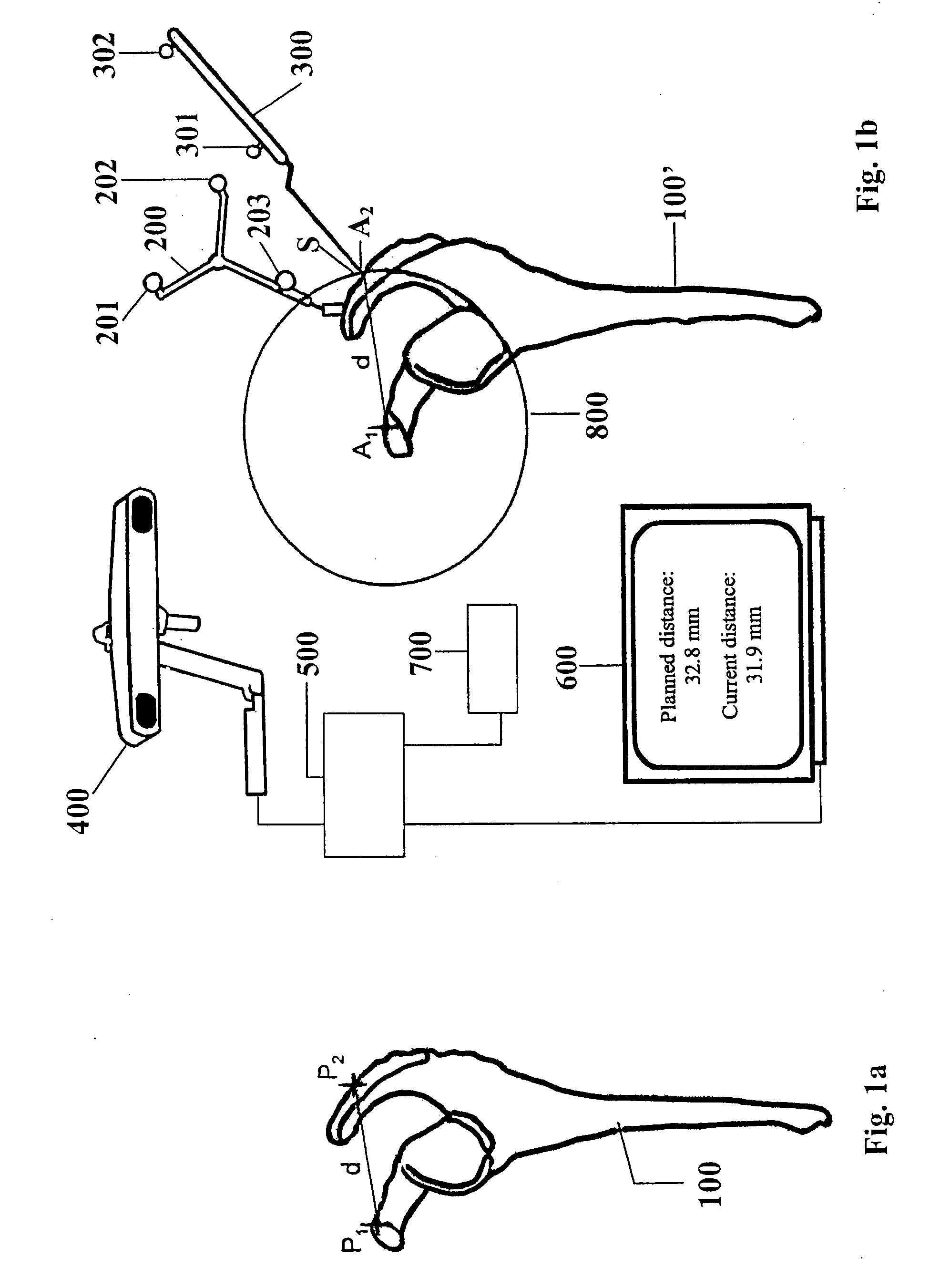
[0054]In the following exemplary embodiment, it is assumed that CT data is available as virtual data of the body structure and it is assumed that first and second landmarks have already been planned (e.g., defined in the virtual space based on the CT data). These first and second landmarks P1 and P2 are shown in FIG. 1a and are spaced by a line “d”. Since CT-based registration is a rigid registration, the distances (for example, the relative distance relationships) are maintained. The distances between the landmarks on the actual body structure, which may be determined intra-operatively, should be the same for the corresponding landmarks. A virtual body structure 100 in FIG. 1a corresponds to an actual body structure 100′ in FIG. 1b. A marker device 200 (e.g., a reference star) is attached to the actual body structure 100′ and is provided with markers (e.g., marker spheres) 201, 202 and 203 that may have predetermined positional relationships to each other. A pointer 300, that likew...


PUM


Abstract

A system and method for determining the position of correspondence object pairs including A-objects and B-objects that represent the same objects of the same anatomical body structure in two different reference frames A and B, including: defining A-objects and B-objects that each represent different objects of the body structure in their respective reference frames; determining geometric relationship data A and geometric relationship data B that describe a geometric relationship between the A-objects based on positions of the A-objects in the reference frame A and the B-objects in the B reference frame; and providing data derived or extracted from the geometric relationship data A and from the geometric relationship data B to allow a comparison of a geometric relationship between at least two A-objects to a geometric relationship between at least two B-objects.

Description

RELATED APPLICATION DATA [0001]This application claims priority of U.S. Provisional Application No. 60 / 950,703 filed on Jul. 19, 2007, and EP07111415 filed on Jun. 29, 2007, which are incorporated herein by reference in their entirety.FIELD OF THE INVENTION[0002]The invention relates to determining correspondence object pairs, which represent the same objects of the same anatomical body structure in different reference frames. The determined correspondence object pairs can be used to enable navigation relative to an anatomical body structure.BACKGROUND OF THE INVENTION[0003]A correspondence object pair describes the same object of an anatomical body structure in two different reference frames. So-called anatomical landmarks may be used as the objects since they are easy for the physician to identify in the anatomical body structure. In accordance with the invention, not only landmarks but any other objects, including parts of the anatomical structure or geometric primitives that hav...

Claims


Application Information

Patent Timeline
IPC IPC(8): G06K9/00
CPCA61B19/50A61B19/52A61B19/5244A61B19/56A61B2017/00725A61B2019/566A61B2019/505A61B2019/5227A61B2019/5255A61B2019/5268A61B2019/5289A61B2019/461A61B90/36A61B2034/2055A61B2034/2068A61B2034/256A61B34/20A61B34/25A61B2090/364A61B2090/061A61B34/10A61B2034/105A61B2090/371
Inventor HAIMERL, MARTINGRUNSCHLAGER, FRANKHEPKE, MARKUSFLEIG, OLIVERHABERL, MARTIN
Owner SMITH & NEPHEW INC
Learn More