Periodic contrast injections and analysis of harmonics for interventional X-ray perfusion imaging

a perfusion imaging and contrast injection technology, applied in the field of perfusion imaging apparatuses, can solve the problems of inability to meet the needs of c-arm type interventional imaging systems, tomographic dynamic perfusion imaging methods for slow rotating interventional imaging systems, where spatial resolution is substantially preserved, and achieve the effects of avoiding or eliminating signal aliasing, reducing temporal signal aliasing, and reducing signal aliasing

Inactive Publication Date: 2017-05-09
KONINKLJIJKE PHILIPS NV
View PDF3 Cites 0 Cited by
  • Summary
  • Abstract
  • Description
  • Claims
  • Application Information

AI Technical Summary

Benefits of technology

[0013]The apparatus further comprises a control unit configured to use the received sampling frequency to generate a control signal for an injector unit to deliver the contrast agent to the object at a variable discharge or injection rate. The control signal, when applied to the injector unit, causes the contrast agent injection rate to vary over time according to a periodic signal of pulses. The periodicity of the pulsed signal is computed by the controller as a function of the sampling rate or frequency so as to mitigate temporal signal aliasing in the X-ray attenuation signal sample.
[0014]Put differently, the contrast material is injected into a patient's vascular system by controlling a power injector (“pump”) in a predefined repeated, periodic manner instead of a single bolus injection. The repeated contrast signal has a frequency-discrete spectrum and is distinguished from the continuous spectrum of a single bolus injection. The specification of the repeated injections, that is periodicity and pulse width, is adjusted to the speed of the C-arm system. The injection periodicity is selected to avoid or at least substantially mitigate or eliminate signal aliasing caused by the low rotation speed of the C-arm system. Aliasing would cause the TAC sample to include the aliasing frequencies as spurious components thereby rendering the subsequent reconstruction and estimation of the perfusion parameters less accurate. In other words the apparatus for supporting perfusion imaging makes use of a specific contrast injection protocol that allows extracting dynamic perfusion parameters such as Blood Flow and Mean Transit Time on a sufficient level of accuracy. The method takes into account the slow rotational speed of a C-arm based X-ray system which must be capable of repeated forward / backward short scan sweeps. As proposed herein the controller is configured to account for image acquisition gaps (i.e. delay times) at the C-arm's turning points.
[0015]The apparatus affords improved workflow for many X-ray guided interventional procedures. The apparatus allows substantially fully temporally resolved quantitative perfusion imaging without the need for fast rotational image acquisitions. In other words, dynamic perfusion parameters measuring the velocity of blood flow (such as CBF) can be obtained so there is no restriction to mere static perfusion parameters such as CBV where it is only the blood concentration that is captured.
[0018]According to one embodiment the controller is configured to control the injector to deliver the contrast agent in a phase prior to commencement of the image acquisition session by the scanner. This avoids recording transient features that occur shortly after injection. The delay allows the contrast agent to settle before commencing with the image acquisition.
[0020]According to one embodiment the family of basis functions includes a linearly rising function. This allows accounting for the long-term accumulation of contrast agent because this effect has been observed to result in step-wise increase of contrast levels as recorded by the TAC.
[0026]By “interventional” X-ray imaging system, such as a C-arm scanner, is meant any rotational imaging system with relatively slow rotation of X-ray source / detector assembly. The rotation is slow if during imaging acquisition session, medial personal can safely operate on the imaged subject in close physical proximity without running the risk of being accidently hit by rotating components in a manner that would cause injury or harm to the personal.

Problems solved by technology

However, tomographic dynamic perfusion imaging methods for slowly rotating interventional imaging systems (for example of the C-arm type) where spatial resolution is substantially preserved are currently not available.

Method used


Image

  • Periodic contrast injections and analysis of harmonics for interventional X-ray perfusion imaging
  • Periodic contrast injections and analysis of harmonics for interventional X-ray perfusion imaging
  • Periodic contrast injections and analysis of harmonics for interventional X-ray perfusion imaging

Examples


Embodiment Construction

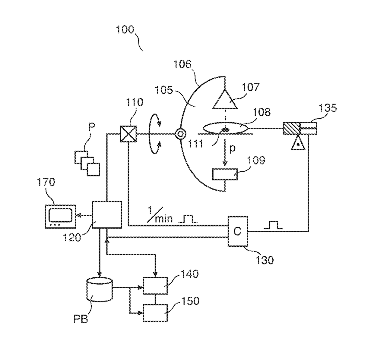
[0036]With reference to FIG. 1, there is shown a perfusion imaging arrangement 100.

[0037]It includes an x-ray imager 105 of the C-arm type. X-ray imager 105 is used to acquire a sequence of x-ray projection images P of an organ of interest 111 to support an intervention.

[0038]In one embodiment, the organ of interest is a patient 108's heart or brain.

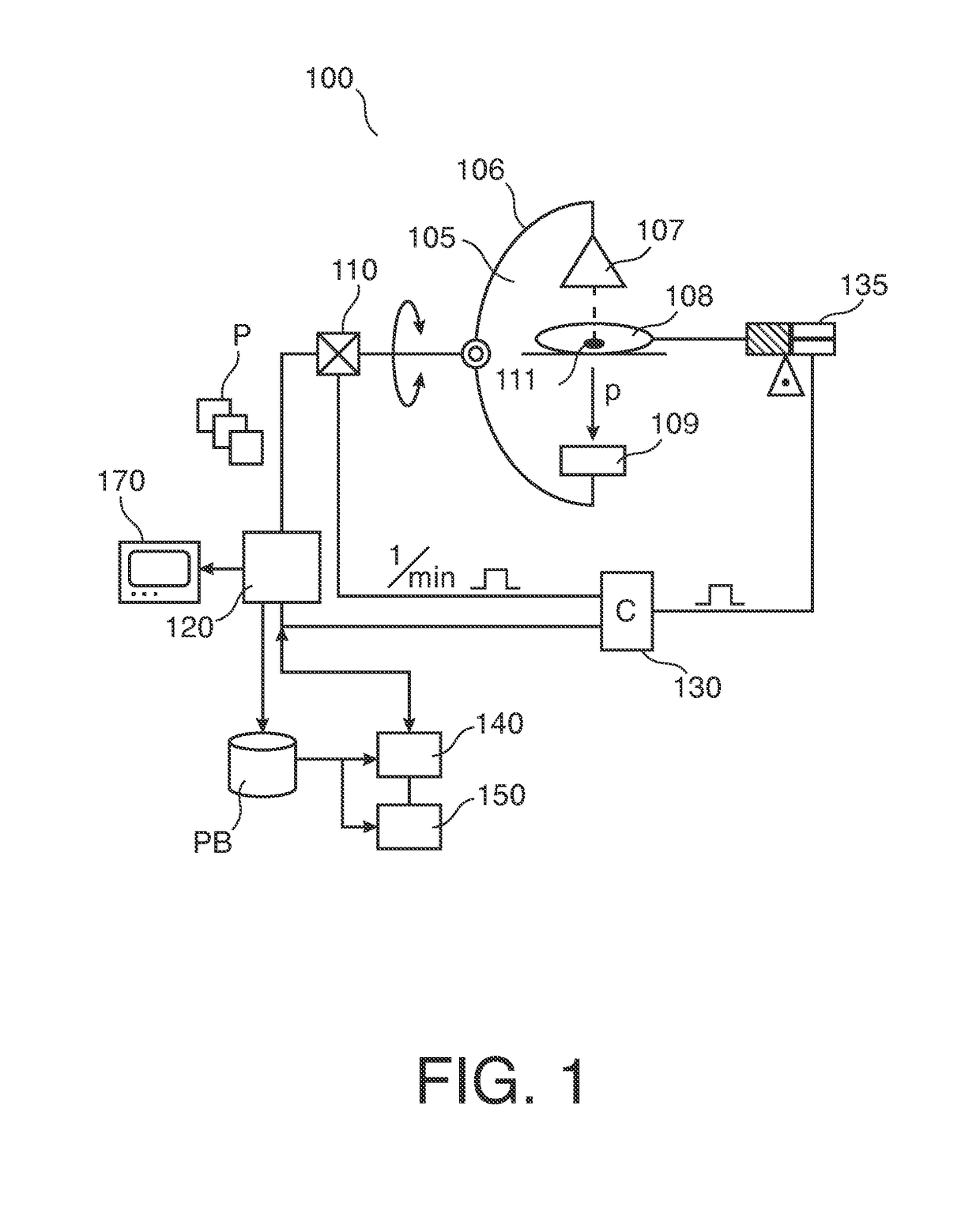
[0039]Patient 108 is placed on an examination table. Imager 105 comprises a rigid C-arm structure 106 journaled on a bearing. Journaling allows rotation of C-arm 140 around a at least one axis passing through journaling. C-arm structure 106 can thus be positioned at various rotation angles α around organ of interest 111.

[0040]C-arm 106 carries at one of its ends an x-ray source 107 and at the other end a detector 109 in opposed spatial relationship to said x-ray source 107. Detector 109 includes an array of detector cells (not shown).

[0041]During an imaging session, x-rays are emitted from x-ray source 107. X-rays pass through organ of i...


PUM


Abstract

An apparatus (130) and a method for adjusting, in perfusion imaging system, a periodic contrast agent injection rate signal (IS) for an injector (135) as function of an image sampling rate determined by the rotational speed of an X-ray source (107)-detector (109) assembly of an X-ray imager (100). Frequency, periodicity and pulse width of the contrast agent injection rate signal (IS) is adjusted to mitigate temporal signal aliasing in a sample of a time attenuation contrast (TAC) signal.

Description

CROSS-REFERENCE TO PRIOR APPLICATIONS[0001]This application is the U.S. National Phase application under 35 U.S.C. §371 of International Application Serial No. PCT / IB2013 / 051568, filed on Feb. 27, 2013, which claims the benefit of U.S. Application Ser. No. 61 / 607,044 filed on Mar. 6, 2012. These applications are hereby incorporated by reference herein.FIELD OF THE INVENTION[0002]The present invention relates to an apparatus for supporting perfusion imaging, to a method for supporting perfusion imaging, to a medical x-ray for perfusion imaging, to a computer program element, and to a computer readable medium.BACKGROUND OF THE INVENTION[0003]Perfusion imaging may be used to gain clues on blood perfusion in soft tissue.[0004]Currently, perfusion imaging is used mainly for purely diagnostic purposes where the imaging is achieved by a fast rotating CT system mounted in a closed gantry. Tomographic reconstruction methods are repeatedly applied to projections acquired in a series of fast r...

Claims


Application Information

Patent Timeline
Patent Type & Authority Patents(United States)
IPC IPC(8): A61B5/05A61M5/32A61M5/172A61M5/315A61K49/04A61M5/00A61B6/03A61B6/00A61B6/02
CPCA61M5/007A61B6/025A61B6/032A61B6/4441A61B6/481A61B6/486A61B6/501A61B6/503A61B6/504A61B6/507A61B6/5217A61B6/542A61K49/04A61M5/172A61M5/315A61M5/32A61M2205/33G16H50/30
Inventor NEUKIRCHEN, CHRISTOPHRUIJTERS, DANIEL SIMON ANNA
Owner KONINKLJIJKE PHILIPS NV
Why Eureka
Try Eureka