

Fuel cell
- Summary
- Abstract
- Description
- Claims
- Application Information
AI Technical Summary
Benefits of technology
Problems solved by technology
Method used
Image

Examples
first embodiment
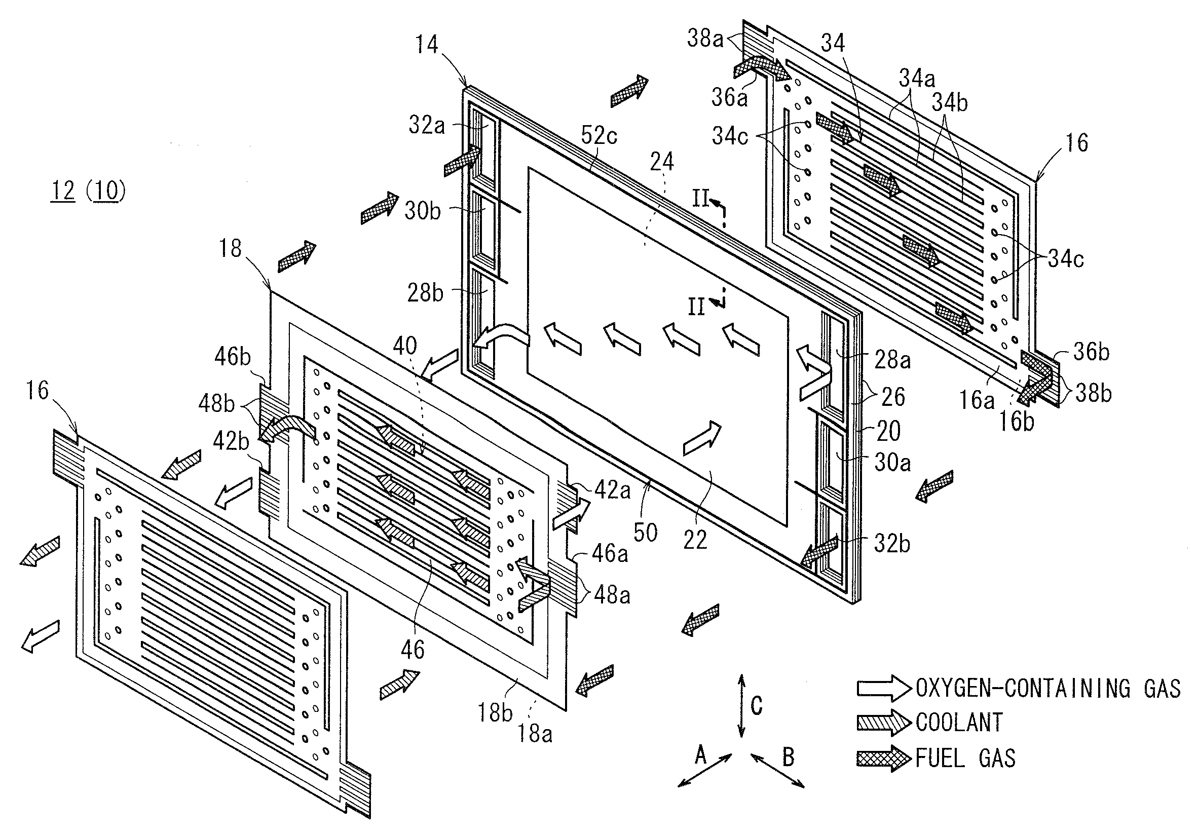
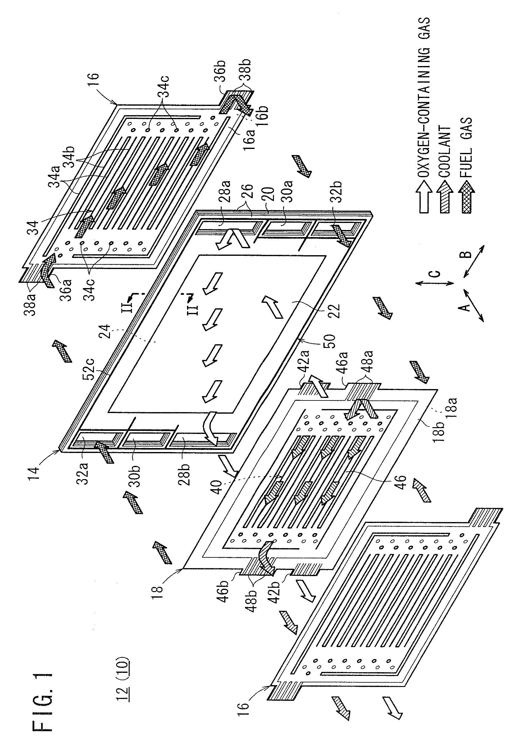
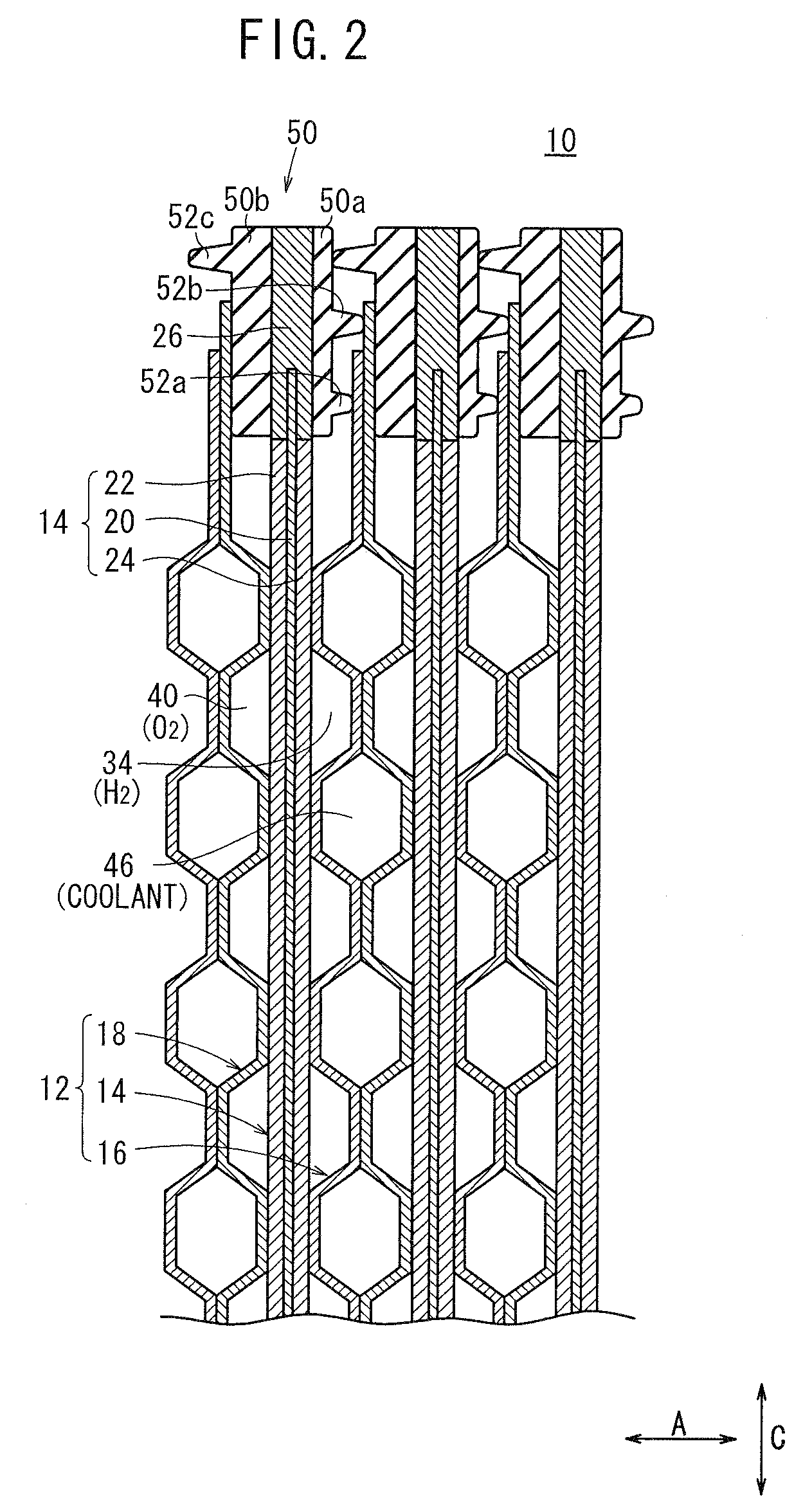
[0028]FIG. 1 is an exploded perspective view schematically showing a fuel cell 10 according to the present invention. FIG. 2 is a cross sectional view showing the fuel cell 10, taken along a line II-II in FIG. 1.
[0029]The fuel cell 10 is formed by stacking a plurality of unit cells (cell units) 12 in a horizontal direction indicated by an arrow A. Each of the unit cells 12 includes a membrane electrode assembly (electrolyte electrode assembly) 14 and a first metal separator 16 and a second metal separator 18 sandwiching the membrane electrode assembly 14.
[0030]For example, the membrane electrode assembly 14 includes a cathode 22, an anode 24, and a solid polymer electrolyte membrane (electrolyte) 20 interposed between the cathode 22 and the anode 24 (see FIG. 2). The solid polymer electrolyte membrane 20 is formed by impregnating a thin membrane of perfluorosulfonic acid with water, for example.
[0031]The surface area of the solid polymer electrolyte membrane 20 is larger than the su...
second embodiment
[0063]FIG. 5 is an exploded perspective view showing a fuel cell 60 according to the present invention. FIG. 6 is a cross sectional view showing the fuel cell 60, taken along a line VI-VI in FIG. 5.
[0064]The constituent elements that are identical to those of the fuel cell 10 according to the first embodiment are labeled with the same reference numeral, and description thereof will be omitted. Further, also in third and fourth embodiments as descried later, the constituent elements that are identical to those of the fuel cell 10 according to the first embodiment are labeled with the same reference numeral, and description thereof will be omitted.
[0065]The fuel cell 60 is formed by stacking a plurality of unit cells (cell units) 62, and each of the unit cells 62 includes a membrane electrode assembly 64, and a first metal separator 66 and a second metal separator 68 sandwiching the membrane electrode assembly 64.
[0066]The first metal separator 66 and the second metal separator 68 are...
third embodiment
[0071]FIG. 7 is an exploded perspective view showing a fuel cell 80 according to the present invention. FIG. 8 is a cross sectional view showing the fuel cell 80, taken along a line VIII-VIII in FIG. 7.
[0072]The fuel cell 80 is obtained by modifying the fuel cell 60 according to the second embodiment to adopt so called skip cooling structure where the coolant flow field 46 is provided for every certain number of membrane electrode assemblies, e.g., every two membrane electrode assemblies 64.
[0073]The fuel cell 80 includes a plurality of cell units 82 stacked in a direction indicated by an arrow A. Each of the cell units 82 is formed by stacking a first metal separator 66, a membrane electrode assembly 64a, an intermediate metal separator 84, the membrane electrode assembly 64, and a second metal separator 68 in the direction indicated by the arrow A.
[0074]The intermediate metal separator 84 has a fuel gas flow field 34 on its surface 84a facing the membrane electrode assembly 64a. T...
PUM
| Property | Measurement | Unit |
|---|---|---|
| Dimension | aaaaa | aaaaa |
Abstract
Description
Claims
Application Information