Method and device for on-line acoustic monitoring of foam and aerated fluid properties

a multi-phase fluid and acoustic monitoring technology, applied in the direction of fluid vibration measurement, fluid pressure measurement by mechanical elements, amplifier modifications to reduce noise influence, etc., can solve the problem of not being able to directly determine the foam quality, high error occurrence, and not being able to direct determine the foam quality distribution

Inactive Publication Date: 2009-01-01
SCHLUMBERGER TECH CORP
View PDF7 Cites 23 Cited by
  • Summary
  • Abstract
  • Description
  • Claims
  • Application Information

AI Technical Summary

Problems solved by technology

Part of the flow should be sent to a bypass pipeline for forming a side flow to determine the foam quality in the flow; this deems to be a disadvantage of the system described above.
The system does not allow the determination of the foam quality directly in the pipeline a fluid from the underground formation passes through.
The application of a separator while defining the foam quality is a reason of high error occurrence.
The disadvantage of this method is that, when it's required to define the foam quality, first it is necessary to converse vapor into a stable foam and then to take off part of the flow to the bypass pipeline, from which samples are then taken.
In case of the foam flow branching, e.g., during the formation hydraulic fracturing or well cementing activities, this method does not allow direct determination of the foam quality distribution.
These measurements are impossible in industrial conditions, when monitoring of remote inaccessible sections (through which foam supply is arranged) is required.
However, known methods and devices do not allow to determine the quality of a foam, which is used in, e.g., well cementing or hydraulic fracturing of formations or in other industries, in the real time mode by conducting acoustic measurements.

Method used


Image

  • Method and device for on-line acoustic monitoring of foam and aerated fluid properties
  • Method and device for on-line acoustic monitoring of foam and aerated fluid properties
  • Method and device for on-line acoustic monitoring of foam and aerated fluid properties

Examples


Embodiment Construction

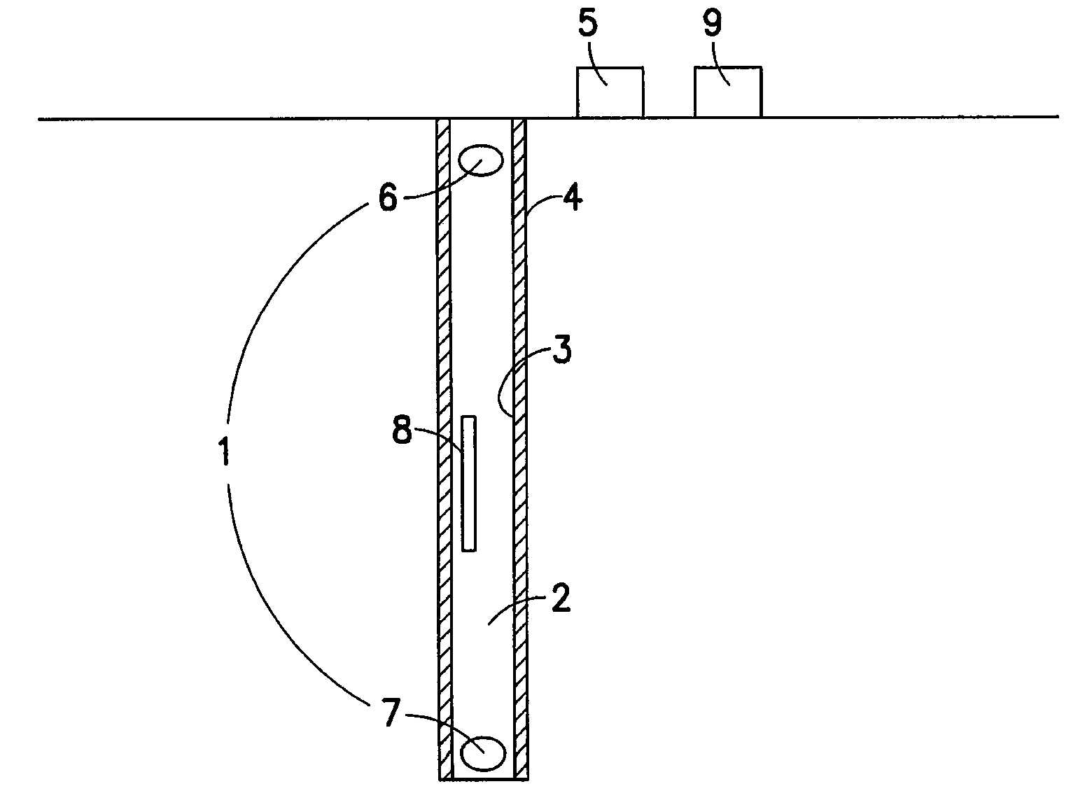
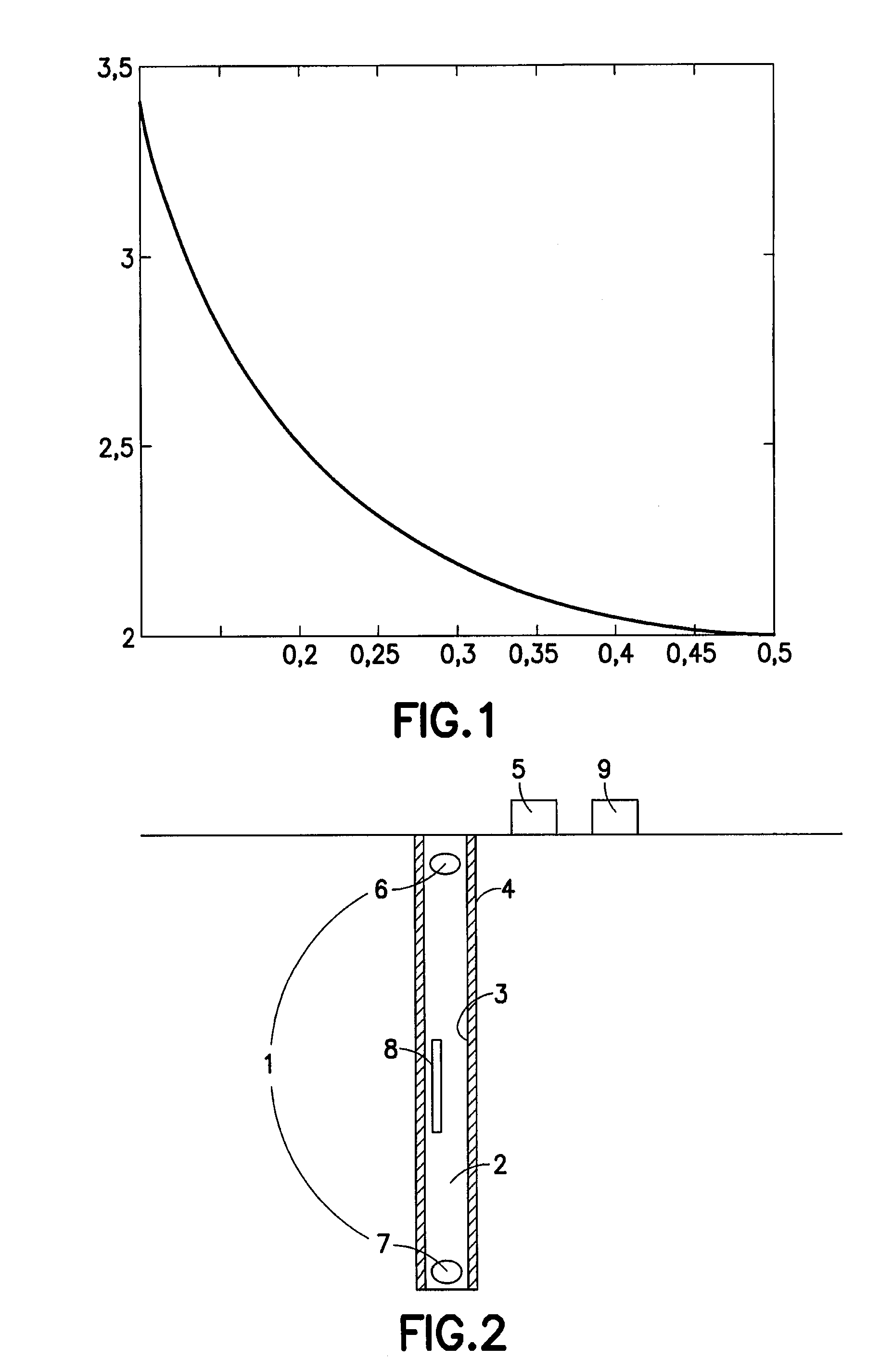
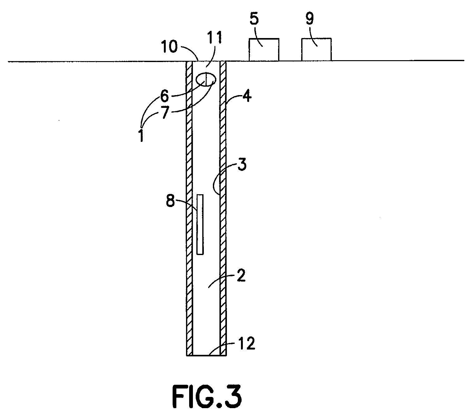
[0049]A device for on-line foam quality acoustic monitoring is shown in FIG. 2 and includes at least one emitter-receiver pair (1) located in the close vicinity of the foam flow (2) and intended to emit at least one acoustic pulse and to receive the acoustic response. The foam flow passes through a pipe (3) in the well (4). The device also includes the logger (5) to record the time required for acoustic pulse to travel from the emitter (6) to the receiver (7). The pressure transducer (8) is mounted between the emitter (6) and the receiver (7). The device also includes the data processing unit (9) connected with at least one emitter (6) / receiver (7), logger (5) and pressure transducer (8) and is designed to calculate speed of sound based on the acoustic pulse arrival time and to calculate the foam quality G based on data received as per equation (3) in case of a foam composed of a perfect gas and a perfect fluid, or in more complicated cases, it can be found from the Value Spreadshee...


PUM

PropertyMeasurementUnit
sound speedaaaaaaaaaa
travel timeaaaaaaaaaa
acoustic pulse speedaaaaaaaaaa

Abstract

A method and device for on-line foam quality acoustic monitoring are suggested. As per the invention, the method provides for the following: at least one emitter / receiver pair is placed in a close vicinity to the foam flow; at least one acoustic pulse is emitted; time, within which the acoustic pulse overcomes the way from the emitter to the receiver, is recorded; acoustic pulse speed (sound speed) is determined by analyzing an acoustic response of the receiver. After that, pressure in the foam in the area between the emitter and receiver is defined and the foam quality Γ is calculated as per the equation:Γ=12±14-NρflpCfm2,where: Cfm—speed of sound in the foam, p—pressure, ρfl—fluid density, Γ—foam quality, N—polytrophic expansion coefficient (N=1 for isothermal process; N=1.4 for adiabatic process), in case of a foam composed of a perfect gas and a perfect fluid for cases, when the foam quality is supposedly much lower than ½ or much bigger than ½, the sign to be selected in the said formula is <<−>> and <<+>>, respectively; in cases when both values of Γ are near ½, the both quality values should be considered as a possible option, or in more complicated cases, it can be found from the Value Spreadsheet

Description

FIELD OF THE INVENTION[0001]This invention relates to the method and device for on-line acoustic monitoring of properties of foams and aerated multi-phase fluids with a complex rheology. This invention can be applied for on-line detection of the quality of foams and aerated fluids, i.e. the assessment of the gas fraction in gas-containing fluids, in particular, in the oil production sector during well maintenance activities, including well cementing or formation fracturing operations. This invention can be implemented in any field of the industry, e.g., in the food industry to produce carbonated beverages as well as in the pharmaceuticals industry.BACKGROUND OF THE INVENTION[0002]Definition: a ratio of a volume of gas contained in a fluid to the total volume of fluid and gas is called as the “quality” and is designated as “Γ”.Γ=V1V,(1)where: V1—gas volume, V—total fluid & gas volume.[0003]As follows from the definition, Γ falls within a range of 0 to 1. If Γ<0.5, the fluid is cal...

Claims


Application Information

Patent Timeline
Patent Type & Authority Applications(United States)
IPC IPC(8): G01N29/024G01H3/00E21B47/00G01N29/00
CPCG01H5/00G01N29/02G01N2291/102G01N2291/02433G01N2291/02836G01N29/07
Inventor SEGAL, ARKADY YUREVICHTHIERCELIN, MARK JEAN
Owner SCHLUMBERGER TECH CORP
Why Eureka
Try Eureka