Standing wave gas-liquid phase change thermoacoustic engine driven by low-grade heat source

A low-grade heat source and thermoacoustic engine technology, which is applied in the direction of machines/engines, mechanical power generating mechanisms, mechanical equipment, etc., can solve the problems of low energy density, high temperature of driving heat source, and difficulty in directly using low-grade heat source, etc., to achieve Realization of miniaturization and optimization of acoustic impedance

Active Publication Date: 2016-08-31
ZHEJIANG UNIV
View PDF4 Cites 0 Cited by
  • Summary
  • Abstract
  • Description
  • Claims
  • Application Information

AI Technical Summary

Problems solved by technology

[0006] However, analyzing the working mechanism and technical status of the existing gas working fluid thermoacoustic engines, it can be found that they have problems such as the high temperature of the driving heat source (usually higher than 300°C), which makes it difficult to directly use low-grade heat sources, and the relatively small energy density leads to The large volume of the system and other shortcomings limit its practical application, which is an important problem to be solved urgently in the research field of thermoacoustic engines.

Method used


Image

  • Standing wave gas-liquid phase change thermoacoustic engine driven by low-grade heat source
  • Standing wave gas-liquid phase change thermoacoustic engine driven by low-grade heat source
  • Standing wave gas-liquid phase change thermoacoustic engine driven by low-grade heat source

Examples


Embodiment Construction

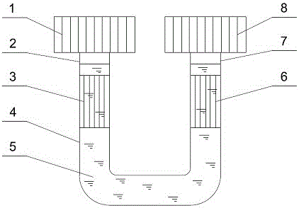
[0016] as attached figure 1 As shown, the standing wave gas-liquid phase change thermoacoustic engine driven by a low-grade heat source includes a first heater 1, a first thermal buffer tube 2, a first cooler 3, a U-shaped tube 4, and a second cooling tube connected in sequence. 6, the second heat buffer tube 7, the second heater 8, the U-shaped tube 4 is provided with a liquid piston 5.

[0017] The liquid piston 5 is difluoromethane CH 2 f 2 , Ammonia NH 3 , Pentafluorochloroethane CF 2 ClCF 3 , Octafluoropropane CF 3 CF 2 CF 3 , the system space above the liquid level of the liquid piston is the vapor of the working medium of the liquid piston.

[0018] Compared with the traditional thermoacoustic engine using gas working medium, the liquid piston working medium in the thermoacoustic engine of the present invention will undergo a gas-liquid phase change process, so it is very important to choose a reasonable liquid piston working medium. Under the temperature condi...


PUM


Abstract

The invention discloses a low-grade heat source driven standing wave type gas and liquid phase change thermoacoustic engine. The thermoacoustic engine comprises a first heater, a first thermal buffering pipe, a first cooler, a U-shaped pipe, a second cooler, a second thermal buffering pipe and a second heater which are connected sequentially, wherein a liquid piston is arranged in the U-shaped pipe. The thermoacoustic exchange is realized based on a gas and liquid phase change thermoacoustic effect, and the ideal thermodynamic cycle can be approximately two isobaric processes and two adiabatic processes. Compared with the conventional gas medium thermoacoustic engine system, the thermoacoustic engine has the characteristics that the temperature difference of cold and heat sources is low, the thermoacoustic engine can run in small temperature difference and at a large pressure ratio, and the low-grade heat source can be utilized; the energy density of unit volume is high, so that the system can be miniaturized; and the gas and liquid coupled oscillation can be realized, and the acoustic impedance of the thermoacoustic engine system can be optimized by comprehensively utilizing the compressibility of gaseous medium, and the high-density mass inertia of the liquid medium.

Description

technical field [0001] The invention relates to a heat engine device, in particular to a thermoacoustic engine driven by a low-grade heat source. Background technique [0002] The thermoacoustic engine is also called a thermoacoustic compressor, or a thermoacoustic driver. It is only composed of a heat exchanger and a pipe section. It has no mechanical moving parts except for the alternating fluid working fluid. Therefore, it has a simple structure, stable and reliable operation, and a long life. Longevity and other characteristics have attracted the attention of academia and industry. [0003] Thermoacoustic engines usually use gas as the working medium, and use the thermal interaction between the gas sound field and the solid boundary in the regenerator (or plate stack) to convert thermal energy into mechanical energy. When the temperature gradient of the device (or plate stack) is greater than the critical value, the gas working medium will produce self-excited oscillati...

Claims


Application Information

Patent Timeline
Patent Type & Authority Patents(China)
IPC IPC(8): F03G7/00
Inventor 汤珂李康金滔黄盛超黄迦乐
Owner ZHEJIANG UNIV
Why Eureka
Try Eureka